Supercharge Your Innovation With Domain-Expert AI Agents!

Logarithmic current-to-voltage conversion circuit with temperature compensation function

A technology of temperature compensation and positive temperature coefficient, applied in the architecture with a single central processing unit, thermometers, thermometers with direct heat-sensitive electrical/magnetic components, etc., can solve the problem of temperature stability of logarithmic signal conversion devices and other issues, to achieve the effect of highlighting substantive characteristics and stabilizing temperature changes

Active Publication Date: 2019-07-09
3PEAK INC
View PDF4 Cites 2 Cited by
  • Summary
  • Abstract
  • Description
  • Claims
  • Application Information

AI Technical Summary

Problems solved by technology

[0004] The purpose of the present invention is to propose a logarithmic flow conversion circuit with temperature compensation function to solve the problem of temperature stability of logarithmic signal conversion devices

Method used


Image

  • Logarithmic current-to-voltage conversion circuit with temperature compensation function
  • Logarithmic current-to-voltage conversion circuit with temperature compensation function

Examples


Embodiment Construction

[0016] The specific implementation of the present invention will be described in further detail below in conjunction with the accompanying drawings of the embodiments, so as to make the technical solution of the present invention easier to understand and grasp, so as to define the protection scope of the present invention more clearly.

[0017] Aiming at the shortcomings of the traditional structure of the existing logarithmic flow conversion circuit, the designers of the present invention have integrated years of experience in this industry, and are committed to seeking a breakthrough in the all-round optimization of the circuit performance, so that the device can adapt to temperature changes in the operating environment, and is highly efficient and stable. To achieve signal conversion.

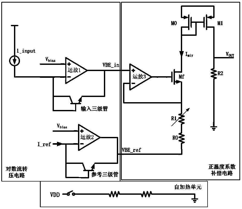
[0018] For a more concrete understanding, such as figure 1 The schematic diagram of the circuit structure of the embodiment of the logarithmic flow conversion circuit with temperature compen...


PUM


Abstract

The invention discloses a logarithmic current-to-voltage conversion circuit with a temperature compensation function. The circuit comprises a logarithm stream voltage transformation buffer unit, a positive temperature coefficient compensation unit and a self-heating unit, the logarithm stream voltage transformation buffer unit is provided with a reference circuit consistent with a basic logarithmcircuit, and a difference value Vbe between the output of the basic logarithm circuit and the output of the reference circuit correspondingly reflects a temperature coefficient; the positive temperature coefficient compensation unit is provided with a first-stage voltage-to-current circuit and a second-stage current mirror; a voltage Vout is output through an external resistor R2, the input end ofthe positive temperature coefficient compensation unit is connected with Vbe, a resistor R0 and an adjustable resistor R1 which are connected in series are arranged in the voltage-to-current circuit,and the value of the adjustable resistor R1 is adjusted to correct the temperature coefficient of (R1 + R0) / R2. By applying the circuit structure design, the temperature compensation is completely realized in a chip, so that a system applying the circuit can be integrated by a single chip, and the simulation result of the circuit shows that the output is more stable along with the temperature change.

Description

technical field [0001] The invention relates to a circuit design with temperature compensation function implemented in the form of an integrated circuit, in particular to a logarithmic current conversion circuit with temperature compensation function. Background technique [0002] With the rapid development of electronic application technology and the development of the hardware foundation, microelectronics is also constantly breaking through and developing in the face of emerging technical problems. In the microelectronic design of many application systems, especially on the basis of the photoelectric conversion hardware developed in the communication field, the current input to the microelectronic system after signal conversion is usually a current with a very large dynamic range, and it needs to be converted for further system operations is a voltage signal. Most of the existing traditional solutions use the architecture of operational amplifier combined with triode to r...

Claims


Application Information

Patent Timeline
IPC IPC(8): G06F17/50G06F15/78G06F7/556
CPCG06F15/7807G06F7/556G06F30/39G01K7/01G05F3/30G05F3/267
Inventor 石传波
Owner 3PEAK INC
Features
  • R&D
  • Intellectual Property
  • Life Sciences
  • Materials
  • Tech Scout
  • Unparalleled Data Quality
  • Higher Quality Content
  • 60% Fewer Hallucinations
Learn More