Organic electroluminescent device

An electroluminescent device and luminescent technology, which are applied in organic semiconductor devices, electric solid devices, organic chemistry, etc., can solve the problems of limited application, short life, and efficiency roll-off, so as to improve utilization, increase life, and reduce The effect of efficiency roll-off

Active Publication Date: 2019-07-09
KUNSHAN GO VISIONOX OPTO ELECTRONICS CO LTD +1
View PDF7 Cites 7 Cited by
  • Summary
  • Abstract
  • Description
  • Claims
  • Application Information

AI Technical Summary

Problems solved by technology

However, the efficiency roll-off of TADF materials reported so far is serious and the lifespan is short, which limits its application in full-color display and white lighting.
[0006] Compared with traditional wide-gap hosts, when TADF or exciplexes are used as hosts to sensitize traditional fluorescence, the triplet T 1 The exciton transitions to the singlet state S by reverse intersystem crossing 1 move up to The energy transfer method transfers energy to the singlet S of the fluorescent material 1 Luminescence greatly improves the exciton utilization rate of fluorescent dyes, but it still faces problems such as serious efficiency roll-off and short lifespan.

Method used


Image

  • Organic electroluminescent device
  • Organic electroluminescent device
  • Organic electroluminescent device

Examples


Embodiment 1

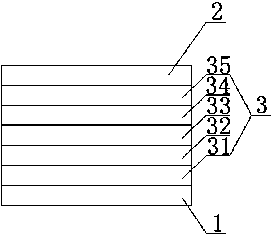
[0046] This embodiment provides an organic electroluminescent device, such as figure 1 As shown, there are a first electrode 1 , a second electrode 2 and an organic functional layer 3 between the first electrode 1 and the second electrode 2 . The first electrode 1 is an anode, the second electrode 2 is a cathode, and the organic functional layer 3 includes a hole injection layer 31, a hole transport layer 32, a light emitting layer 33, an electron transport layer 34 and an electron injection layer 35 that are stacked, that is, the The structure of the organic electroluminescent device is: anode / hole injection layer / hole transport layer / light emitting layer / electron transport layer / electron injection layer / cathode.

[0047]The light-emitting layer 33 is composed of a host material and a dopant material doped in the host material. The wide bandgap material and the exciplex constitute the host material by co-evaporation, and the donor molecules and acceptor molecules are co-evapo...

Embodiment 2

[0068] In embodiment 2, the OLED device can be designed as the following organic electroluminescent device, the structure of the organic electroluminescent device includes an anode, a hole injection layer, a hole transport layer, an organic light emitting layer, an electron transport layer, an electron injection layer and the cathode. In this example, a compound containing a fluorenyl group is used as a bandgap material for the cell, which has a structure as shown in formula (W-25):

[0069]

[0070] A compound containing phenyl and carbazolyl is selected as the donor molecule, which has the structure shown in formula (D-1):

[0071]

[0072] A compound containing triazine, phenyl, and diphenylphosphono is selected as the acceptor molecule, and has a structure as shown in formula (A-6):

[0073]

[0074] The above-mentioned donor molecule having the structure shown in formula (D-1) and the acceptor molecule having the structure shown in formula (A-6) constitute an ex...

Embodiment 3

[0084] This embodiment provides an organic electroluminescent device, the structure of which is the same as that of embodiment 1. The only difference between the organic electroluminescent device and the organic electroluminescent device provided in embodiment 1 is that the hole transport layer is changed from TAPC to NPB, Its molecular structure is:

[0085]

[0086] The host material in the light-emitting layer is selected from a wide bandgap material having a structure shown in formula (W-19) and a donor molecule having a structure shown in formula (D-2) and having a structure shown in formula (A-10) The excimer complex formed by the acceptor molecule of the structure, the doping material is a fluorescent doping dye with a structure shown in formula (F-10):

[0087]

[0088] In the organic light-emitting layer 33, the exciplex formed by the donor molecule having the structure shown in formula (D-2) and the acceptor molecule having the structure shown in formula (A-10)...


PUM


Abstract

The invention belongs to the field of display technologies and particularly discloses an organic electroluminescent device. The organic electroluminescent device comprises a light-emitting layer, wherein the light-emitting layer comprises an exciplex consisting of donor molecules and receptor molecules and a broad-band-gap material used for increasing the spacing between the donor molecules and the receptor molecules. Through the organic electroluminescent device, the HOMO and LUMO track overlapping degree of the formed exciplex can be lowered, singlet-triplet energy level difference is reduced, the reverse intersystem crossing rate (kRISC) of an exciplex body is increased, energy transmission to guest molecules is enhanced, and the efficiency of the device is improved; and meanwhile, by introducing the broad-band-gap material, the concentration of triplet excitons in the light-emitting layer can be effectively lowered, triplet-triplet annihilation (TTA) and triplet-polaron annihilation (TPA) are suppressed, efficiency roll-off is lowered, and the life of the device is prolonged.

Description

technical field [0001] The invention belongs to the field of display technology, and in particular relates to an organic electroluminescent device. Background technique [0002] Organic light-emitting diodes (OLEDs) have great application prospects in the fields of display and lighting due to their ultra-thin, light weight, low energy consumption, active light emission, wide viewing angle, and fast response. more and more people's attention. [0003] In 1987, Deng Qingyun (C.W.Tang) and Vanslyke of Eastman Kodak Company in the United States reported for the first time based on Alq 3 And the double-layer organic electroluminescent device of triarylamine, which opened the research direction of OLED. Traditional fluorescent materials are easy to synthesize, cheap, stable, and have a long device life. However, due to electron spin prohibition, at most 25% of singlet excitons can be used to emit light, and the external quantum efficiency of the device is often lower than 5%. N...

Claims


Application Information

Patent Timeline
Patent Type & Authority Applications(China)
IPC IPC(8): H01L51/50
CPCH10K50/11H10K2101/40H10K50/12C07D209/86C07D401/14C07D403/10C07D471/04C09K11/06C07C13/72C07C2603/94C07D513/04C07C15/28C07C15/38C07C15/20C07C13/62C07C2603/54C07F9/5325C07F9/5728C07F7/0812C07F9/65583C07F9/65522C07F9/6521C07F9/655354C07F5/027H10K85/626H10K85/633H10K85/654H10K85/6572H10K2101/90H10K2101/20C07C2603/44C07C2603/97C07C211/54C07F9/5329C09K2211/1007C09K2211/1011C09K2211/1014C09K2211/1018H10K85/636H10K2101/10
Inventor 段炼宋晓增张东东魏金贝
Owner KUNSHAN GO VISIONOX OPTO ELECTRONICS CO LTD
Why Eureka
Try Eureka