Differential grinding roller type rapid biomass catalytic pyrolysis device and method

A technology of catalytic pyrolysis and biomass, which is applied in the field of differential-speed roller-type rapid catalytic pyrolysis of biomass, can solve the problems of reducing reactor processing efficiency, increasing the cost of biomass processing, and failing to guarantee the catalytic effect, etc., to achieve Compact structure, large specific heat capacity, good catalytic effect

Active Publication Date: 2019-07-12
NORTH CHINA ELECTRIC POWER UNIV (BAODING)
View PDF6 Cites 5 Cited by
  • Summary
  • Abstract
  • Description
  • Claims
  • Application Information

AI Technical Summary

Problems solved by technology

However, due to the poor thermal conductivity of biomass, it is difficult to quickly absorb heat and raise the temperature. At present, it is mainly solved by prolonging the residence time of the particles in the reactor or using finer raw material particles, which will either reduce the processing efficiency of the reactor or reduce the temperature of the reactor. Increasing the power consumption of the pulverizer will increase the cost of biomass treatment
[0004] As for the catalytic pyrolysis technology of biomass, the current mainstream pyrolysis reactors are nothing more than three types: first, for rotating cone, ablation and other moving mechanical reactors, although they can ensure compact structure, low energy consumption, and reduce The amount of carrier gas used even does not use carrier gas, but it is difficult to make the cataly...

Method used


Image

  • Differential grinding roller type rapid biomass catalytic pyrolysis device and method
  • Differential grinding roller type rapid biomass catalytic pyrolysis device and method
  • Differential grinding roller type rapid biomass catalytic pyrolysis device and method

Examples


Embodiment 1

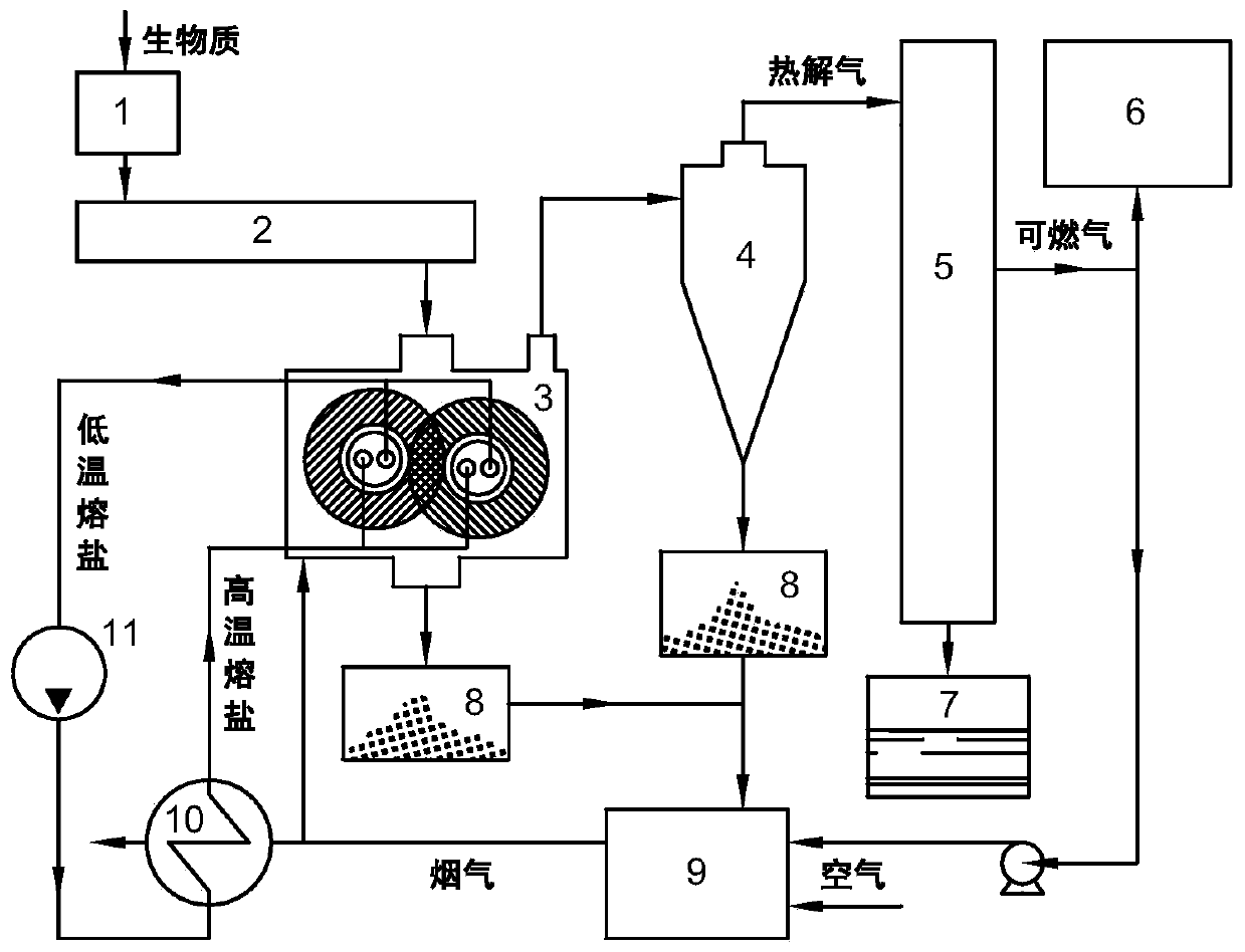
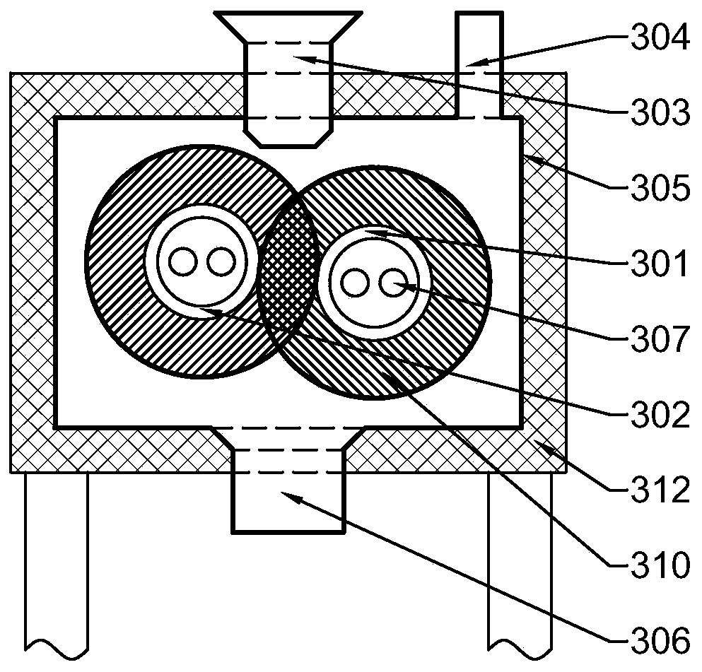
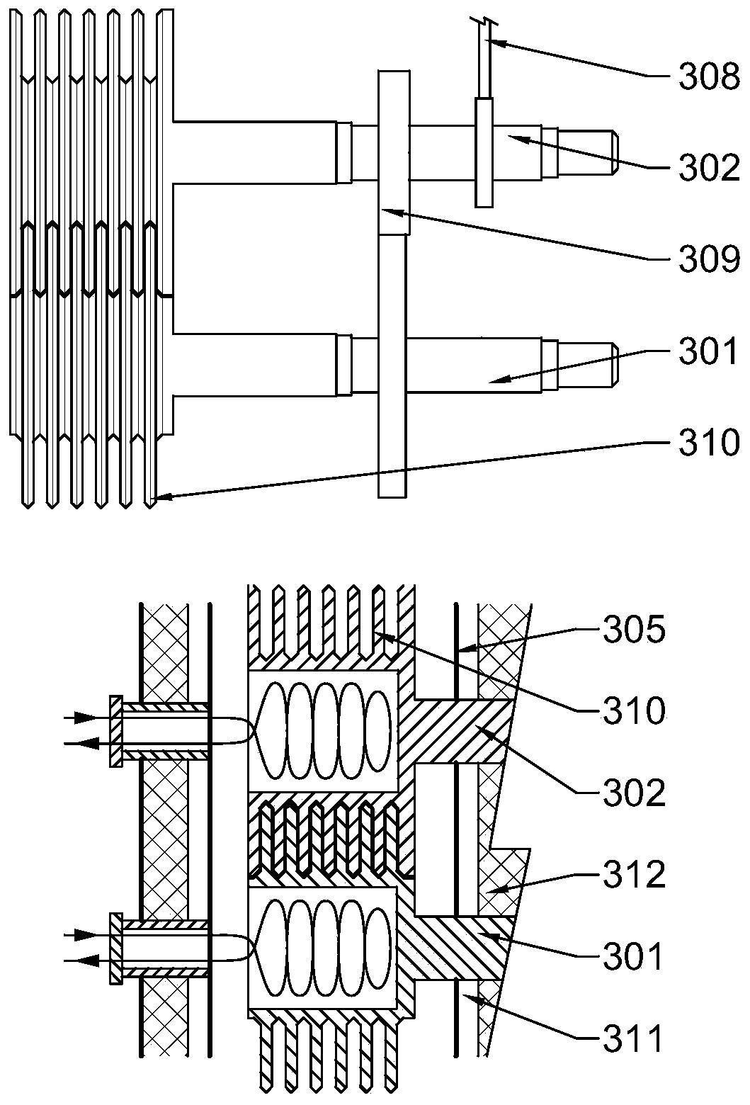
[0049] Bagasse with a moisture content of 8wt% is crushed to an average particle size of 8mm, and enters the differential roller pyrolysis reactor 3 through the screw feed system 2 at a feed rate of 120kg / h; the catalytic layer is activated by steam Activated carbon is extruded onto the surface of the grinding disc, and the friction layer is made of friction coating, such as Figure 4 As shown; by adjusting the power of the motor, the active high-speed roller shaft speed is guaranteed to be 10r / min, and a 4:5 gear transmission is used to drive the low-speed roller shaft speed to 8r / min; enter the high temperature in the differential grinding roller pyrolysis reactor 3 The temperature of the molten salt in the molten salt heat exchange tube 307 is 400°C, and the measured temperature in the pyrolysis reactor is 310°C; the pyrolysis product is separated from the gas-solid and condensed from the pyrolysis gas to obtain the target product 4-ethylphenol The yield of bio-oil, 4-ethyl...

Embodiment 2

[0051] The pine wood with a moisture content of 8wt% is crushed to an average particle size of 8 mm, and then sent into the differential grinding roller pyrolysis reactor 3 after passing through the screw feed system 2 at a feed rate of 100 kg / h; The temperature of the low-speed roller shaft is 15r / min, and the speed of the low-speed roller is 10r / min; the temperature of the molten salt entering the high-temperature molten salt heat exchange tube 307 in the differential grinding roller pyrolysis reactor 3 is 650°C to ensure that the temperature in the pyrolysis reactor is maintained At 500°C; the catalyst of the disc catalyst layer is solid potassium phosphate, and the friction layer is friction coating, such as Figure 4 Shown; After the pyrolysis product is subjected to gas-solid separation and pyrolysis gas condensation, coke, bio-oil and combustible gas three-phase pyrolysis products are obtained, and the respective yields are 29.4wt%, 48.6wt% and 22.0wt%; The content of t...

Embodiment 3

[0053] The corn cob with a moisture content of 8wt% was crushed to an average particle size of 10mm, and then impregnated with ZnCl 2 and dried, ZnCl 2 The loading capacity is 15.4wt%; through the screw feeding system 2 with the feed rate of 100kg / h, the material particles are sent into the differential grinding roller pyrolysis reactor 3, and the speed ratio of the two grinding rollers is 1:2; by adjusting The power of the motor ensures that the speed of the high-speed roller shaft is 10r / min; the temperature of the molten salt entering the high-temperature molten salt heat exchange coil 307 in the differential roller pyrolysis reactor 3 is 440°C, and the temperature in the pyrolysis reactor is 340°C ; After the pyrolysis product is separated from gas and solid and condensed from the pyrolysis gas, coke, bio-oil and combustible gas three-phase pyrolysis products are obtained, and the respective yields are 43.2wt%, 48.1wt% and 8.7wt%, wherein the target product The yield of f...


PUM


Abstract

The invention relates to a differential grinding roller type rapid biomass catalytic pyrolysis device and method. The device comprises a hopper, a feed system, a differential grinding roller type pyrolysis reactor, a gas-solid separation system, a pyrolysis gas condensation system, a bio-oil collection tank, a carbon collection box, a combustion system, a heat exchange system and a fused salt circulation system. The differential grinding roller type pyrolysis reactor comprises a pair of differential grinding rollers, a closed casing, a high-temperature fused salt heat exchange tube, a materialinlet/outlet, a gas outlet, a drive and transmission device and a thermal insulation system. The pretreated biomass raw materials are subjected to heating and shearing friction of cross high-temperature millstones, the surface carbon residues are continuously peeled off, and effective catalytic pyrolysis inside raw material particles is ensured; the pyrolysis gas is rapidly condensed after gas-solid separation so as to obtain high-grade bio-oil fuel or bio-oil enriched in specific high value-added products; meanwhile, the combustible gas and coke are collected and combusted to produce high temperature flue gas, and the flue gas is used for heating the fused salt and conducting heat and further heating the millstone, so that a self-heating pyrolysis process is realized.

Description

technical field [0001] The invention belongs to the technical field of biomass energy utilization, and in particular relates to a device and method for fast catalytic pyrolysis of biomass with a differential grinding roller type. Background technique [0002] Through rapid pyrolysis of biomass raw materials such as agricultural and forestry waste and urban waste, not only can the waste be made harmless, but also high-grade bio-oil and high value-added chemicals can be obtained. Biomass rapid pyrolysis technology converts difficult-to-treat biomass waste into liquid bio-oil and bio-combustible gas with high energy density, which is convenient for its transportation, storage, combustion and modification, and makes better use of biomass raw material waste, reducing pollution emissions from direct combustion. The use of catalysts to regulate the biomass pyrolysis process to obtain bio-oil rich in specific high value-added chemicals, and to obtain the required chemical products ...

Claims


Application Information

Patent Timeline
IPC IPC(8): C10B53/02C10G1/00
CPCC10B53/02C10G1/00Y02E50/10
Inventor 陆强谢文銮吴昱廷李凯杨勇平
Owner NORTH CHINA ELECTRIC POWER UNIV (BAODING)
Why Eureka
Try Eureka