Method for regulating and controlling F-P optical fiber sensor sensitivity through intracavity gas pressure

A technology of optical fiber temperature and gas pressure, applied in thermometers, thermometers with physical/chemical changes, instruments, etc., can solve the problems of inability to control temperature test sensitivity, inability to achieve high-sensitivity test temperature, etc., to achieve easy implementation and simple method , the effect of improving the degree of perception

Inactive Publication Date: 2019-07-19
SHANDONG UNIV
View PDF6 Cites 3 Cited by
  • Summary
  • Abstract
  • Description
  • Claims
  • Application Information

AI Technical Summary

Problems solved by technology

[0004] The manufacture of the optical cavity of the F-P fiber optic sensor is completed during the anodic bonding process of silicon wafer and borosilicate glass. After the bonding is completed, the entire cavity becomes a gas-tight cavity. The existing F-P fiber optic temperature sensor can only serve The purpose of temperature can not achieve the sensitivity of temperature control test, nor can it achieve high sensitive test temperature

Method used


Image

  • Method for regulating and controlling F-P optical fiber sensor sensitivity through intracavity gas pressure
  • Method for regulating and controlling F-P optical fiber sensor sensitivity through intracavity gas pressure
  • Method for regulating and controlling F-P optical fiber sensor sensitivity through intracavity gas pressure

Examples


Embodiment 1

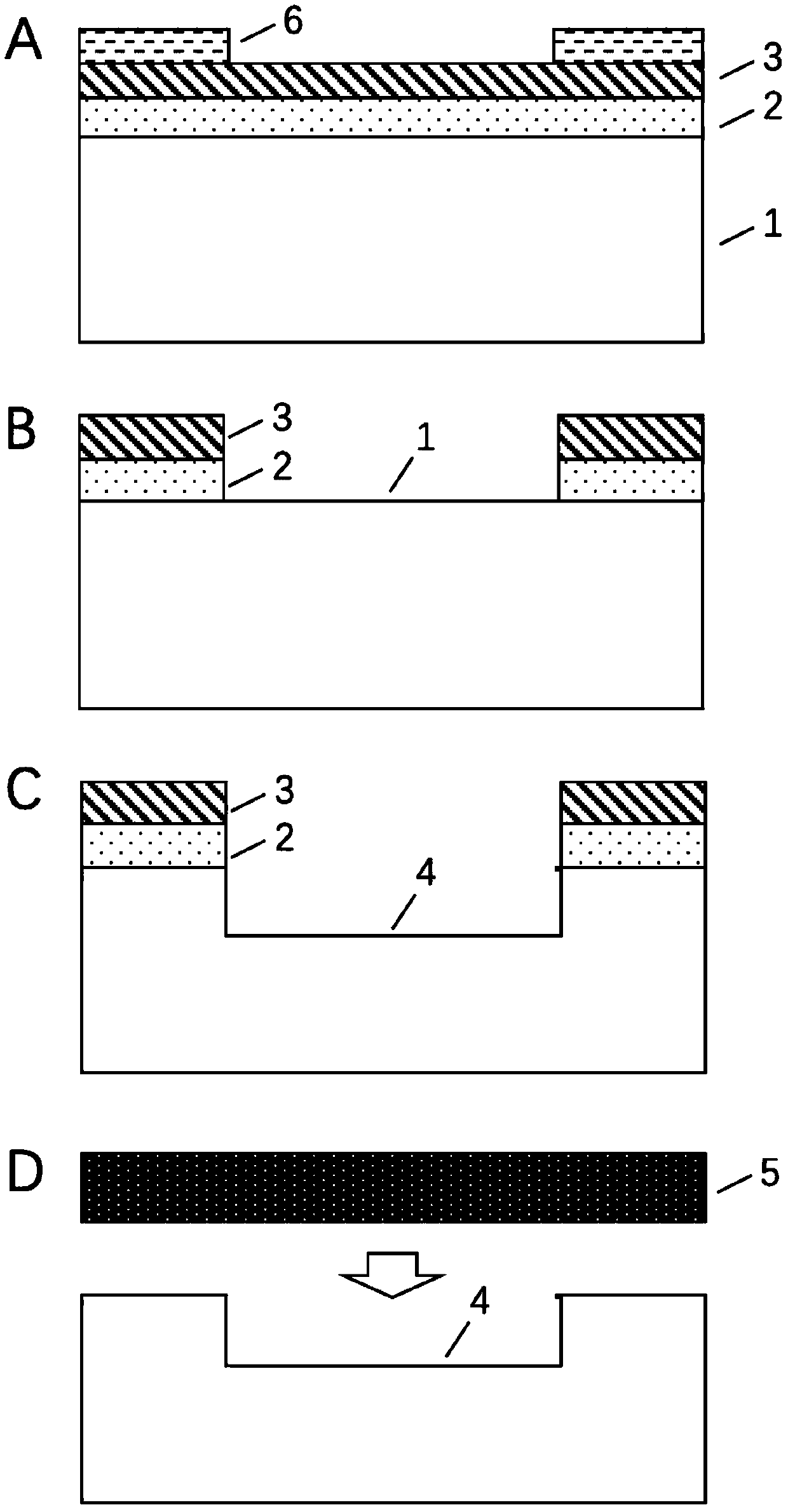
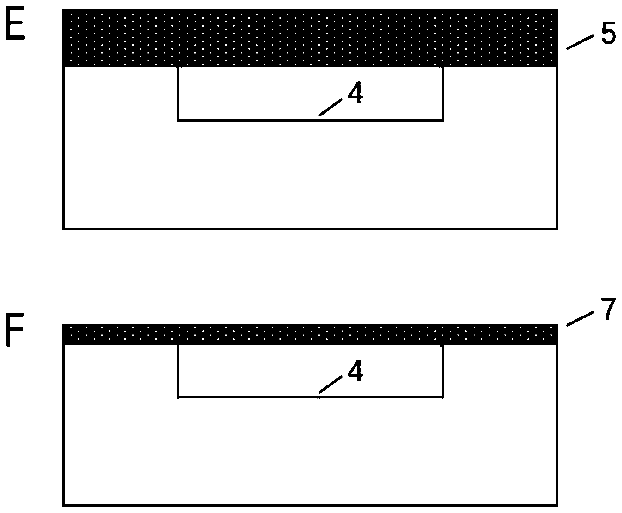
[0046] A method for regulating the sensitivity of an F-P optical fiber temperature sensor through gas pressure in a cavity, comprising the following steps, the process steps are as follows figure 1 Shown:

[0047](1) successively sputtering thickness is the Ni film 2 of 200nm and the Au film 3 of 800nm ​​on the surface of borosilicate glass 1, forms Ni / Au alloy thin film; Layer photoresist positive resist (AZ1500) 6, then align the photoresist plate for exposure and development, and put it into the positive resist developer to wash off the excess; as figure 1 a.

[0048] The patterned borosilicate glass is etched with Au etching solution and Ni etching solution successively, and the etching time is 5 minutes and 1 minute respectively; the Au etching solution is iodine, potassium iodide, water in a mass ratio of 1:5:20 Mixed solution; the Ni corrosion solution is hydrochloric acid with a mass fraction of 10%. After etching, wash off the photoresist mask with acetone to form ...

Embodiment 2

[0053] With the method for regulating the sensitivity of the F-P optical fiber temperature sensor by the gas pressure in the cavity described in Example 1, the difference is that:

[0054] Step (2) During the bonding process, adjust the pressure of the vacuum chamber of the bonding furnace so that the pressure of the vacuum chamber is 0.02 MPa, and prepare a sample with a pressure of 0.02 MPa in the sealed cavity between the silicon wafer and the borosilicate glass.

Embodiment 3

[0056] With the method for regulating the sensitivity of the F-P optical fiber temperature sensor by the gas pressure in the cavity described in Example 1, the difference is that:

[0057] Step (2) During the bonding process, adjust the pressure of the vacuum chamber of the bonding furnace so that the pressure of the vacuum chamber is 0.03 MPa, and prepare a sample with a pressure of 0.03 MPa in the sealed cavity between the silicon wafer and the borosilicate glass.


PUM

PropertyMeasurementUnit
thicknessaaaaaaaaaa
thicknessaaaaaaaaaa
thicknessaaaaaaaaaa

Abstract

The invention discloses a method for regulating and controlling F-P optical fiber sensor sensitivity through intracavity gas pressure. The method comprises the following steps: regulating the pressurein a bonding equipment vacuum chamber by utilizing the anodic bonding process of a silicon wafer and borosilicate glass, wherein the vacuum chamber pressure is 0.01MPz to 0.1MPa; manufacturing a sample with a sealing cavity between the silicon wafer and the borosilicate glass after the bonding, wherein the pressure in the sealing cavity is 0.01MPa to 0.1MPa; and finally obtaining a F-P optical fiber temperature sensor with the pressure in the optical cavity as 0.01MPa to 0.1MPa. Through the method disclosed by the invention, the sensor with different temperature testing sensitivities can be obtained, the sensitivity of the temperature testing can be regulated and controlled, so that a single sensor can satisfy different testing demands in an actual application.

Description

technical field [0001] The invention relates to a method for regulating the sensitivity of an F-P optical fiber temperature sensor through gas pressure in a cavity, and belongs to the technical field of micro-optoelectronic device production. Background technique [0002] Optical fiber sensing technology is a new type of sensing technology that uses light as the carrier and optical fiber as the medium to perceive and transmit external signals (measurands), which has developed rapidly along with the development of optical fiber and optical fiber communication technology. Among them, the F-P optical fiber sensor has the characteristics of small size, simple structure, high measurement accuracy and high sensitivity as a micro-displacement sensor, and has been widely used. F-P fiber optic sensors usually analyze external signals through data such as reflectivity or wavelength, and the physical quantities tested are very wide, such as temperature, pressure, strain, and acoustic f...

Claims


Application Information

Patent Timeline
Patent Type & Authority Applications(China)
IPC IPC(8): G01K11/32G01K11/322
CPCG01K11/32
Inventor 徐现刚王荣堃
Owner SHANDONG UNIV
Why Eureka
Try Eureka