Bit shank manufacturing method

A manufacturing method and technology of shank tails, which are applied in the direction of manufacturing tools, coatings, furnace types, etc., can solve the problems of strong rigidity in the production process, damage to shank tails, and lack of flexibility, so as to save processing time, save money, The effect of reducing finished goods inventory

Pending Publication Date: 2019-07-26
刘艺纯
View PDF5 Cites 2 Cited by
  • Summary
  • Abstract
  • Description
  • Claims
  • Application Information

AI Technical Summary

Problems solved by technology

[0008] The disadvantages of these processing methods are: 1. Treat the shank as an integral part; 2. The length and thread type of the shank must be determined before heat treatment, and cannot be changed after heat treatment. The production process of the product is too rigid and lacks flexibility; 3. 85% of the use, scrap and damage of the shank occur at the threaded end

Method used


Image

  • Bit shank manufacturing method
  • Bit shank manufacturing method

Examples


Embodiment 1

[0073] T45-600 Sandvik HL700 Rock Drill Tail

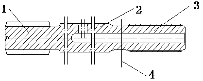
[0074] The length of the male joint is 250mm, the diameter of the shank is 52mm, and 23CrNi3Mo (EN40B) is selected,

[0075] Heat treatment method 1: Carburizing at 930°C, then air cooling, the thickness of the carburized layer is 0.8-1.0mm.

[0076] Spline end material: choose 23CrNi3Mo (EN40B),

[0077] Heat treatment method 1: Carburizing at 930°C, then air cooling, the thickness of the carburized layer is 0.8-1.0mm.

[0078] a: Use friction welding to weld the processed spline end and male joint on the middle mating end;

[0079] b: 840°C annealing treatment at the welding place to remove internal and external welding flashes, that is, welding nodules;

[0080] c: 930 ° C quenching treatment at the welding place again, and then air cooling;

[0081] d: Non-destructive testing of welds;

[0082] e: Straightening and tempering at 240°C to remove straightening stress;

[0083] f: On the cylindrical grinder, grind the planes...

Embodiment 2

[0087] T45-575 Atlas COP1238 Rock Drill Tail

[0088] The length of the male joint is 300mm, the diameter of the shank is 45mm, and 23CrNi3Mo (EN40B) is selected,

[0089] Heat treatment method 1: Carburizing at 930°C, then air cooling, the thickness of the carburized layer is 0.8-1.0mm.

[0090] Spline end material: 25Cr3MnMo (SANBAR 23),

[0091] Heat treatment method 1: Carburizing at 930°C, then air cooling, the thickness of the carburized layer is 0.6-0.8mm.

[0092] a: Use friction welding to weld the processed spline end and male joint on the middle mating end;

[0093] b: 840°C annealing treatment at the welding place to remove internal and external welding flashes, that is, welding nodules;

[0094] c: 930 ° C quenching treatment at the welding place again, and then air cooling;

[0095] d: Non-destructive testing of welds;

[0096] e: Straightening and tempering at 240°C to remove straightening stress;

[0097] f: On the cylindrical grinder, grind the planes at...


PUM


Abstract

The invention discloses a bit shank manufacturing method which comprises the following steps of regarding a bit shank as a divisible part, wherein the bit shank is divided into a left-side spline endand a right-side screw-thread male connector and is formed by combining a left part and a right part; (1) processing the screw-thread male connector; (2) processing the spline end; and (3) processingthe bit shank: A, selecting the spline end matched with a jackdrill, and the corresponding screw-thread male connector; B, using a friction welding machine for welding the spline end, the screw-threadmale connector and a middle cooperation end; C, removing internal and external welding trimmings, namely, welding slags; D, carrying out heat treatment on the welding part again; E, carrying out nondestructive inspection on the welding part; F, straightening and removing the straightening stress; G, feeding on a cylindrical grinding machine, grinding a middle part until the dimension meets the drawing requirement, polishing planes at two ends, and ensuring that the two end surfaces are parallel and perpendicular to a middle axis at the same time; and H, after passing inspection, coating anti-rust oil, packaging and storing. The spline end can be matched with multiple screwed joints, so that the material is saved; flexible and customized production can be realized; and the stock of finished goods in a warehouse is reduced.

Description

technical field [0001] The invention relates to the manufacture of shanks and belongs to the technical field of rock drilling tools. Background technique [0002] The shank tail is the transmission connection part between the rock drill and the threaded rock drill rod (drill rod), English shank\shankadapter. It is also one of the consumables that are largely scrapped at the rock drilling site. At present, the basic manufacturing technology of shank tail at home and abroad is divided into direct processing method of bar material and forging processing method. [0003] Drilling tool steel is divided into: medium and high carbon drilling tool steel, such as 55SiMnMo, 40CrNiMo, etc. The heat treatment method is oil quenching or air cooling after heating. Low-carbon drilling tool steels, such as 23CrNi3Mo (EN40B), 25Cr3MnMo (SANBAR 23), 22SiMnCr2NiMo (FF710), etc., are heat treated by oil quenching after carburizing or air cooling after carburizing. [0004] A: The processing ...

Claims


Application Information

Patent Timeline
Patent Type & Authority Applications(China)
IPC IPC(8): B23P15/00C21D1/18C21D9/00C21D9/50C23C8/00C21D1/26
CPCB23P15/00C21D1/18C21D1/26C21D9/0068C21D9/50C23C8/00
Inventor 刘艺纯刘朋
Owner 刘艺纯
Why Eureka
Try Eureka