Waste heat recycling system for aquarium and working method thereof

A waste heat recovery and marine technology, applied in fluid heaters, clean heat transfer devices, lighting and heating equipment, etc., can solve the problems of increasing the operating cost of the aquarium, consuming large energy, and high labor costs, so as to reduce the frequency of water changes, The effect of reducing energy waste and high energy utilization

Active Publication Date: 2019-08-13
青岛海田设计事务所有限公司
View PDF17 Cites 2 Cited by
  • Summary
  • Abstract
  • Description
  • Claims
  • Application Information

AI Technical Summary

Problems solved by technology

For the aquarium, the life support system is very important. Different marine organisms have different requirements for seawater temperature. Therefore, the life support systems of different aquariums in the aquarium need to be designed separately. Among them, the marine life display pools such as tropical fish and jellyfish need to be heated all year round. , in order to maintain normal survival, in the prior art, lithium bromide units or hot water boilers are generally used to heat it, and replenishing water and maintaining a constant water temperature in the display pool need to consume a lot of energy for heating
However, the seawater discharged from the display pool contains a large amount of waste heat, which causes energy waste, which is not environmentally friendly, but also increases the operating cost of the aquarium; in addition, the replacement of the water in the life support system of the aquarium in the prior art mostly relies on manual water level adjustment. Water temperature monitoring, and manual control of the water pump for water change, water replenishment, etc., the labor cost is high

Method used


Image

  • Waste heat recycling system for aquarium and working method thereof
  • Waste heat recycling system for aquarium and working method thereof
  • Waste heat recycling system for aquarium and working method thereof

Examples


Embodiment 1

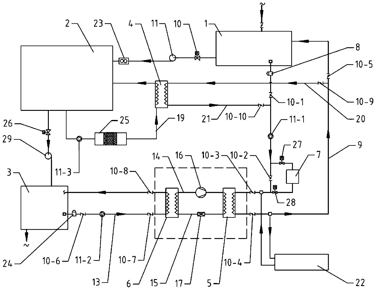
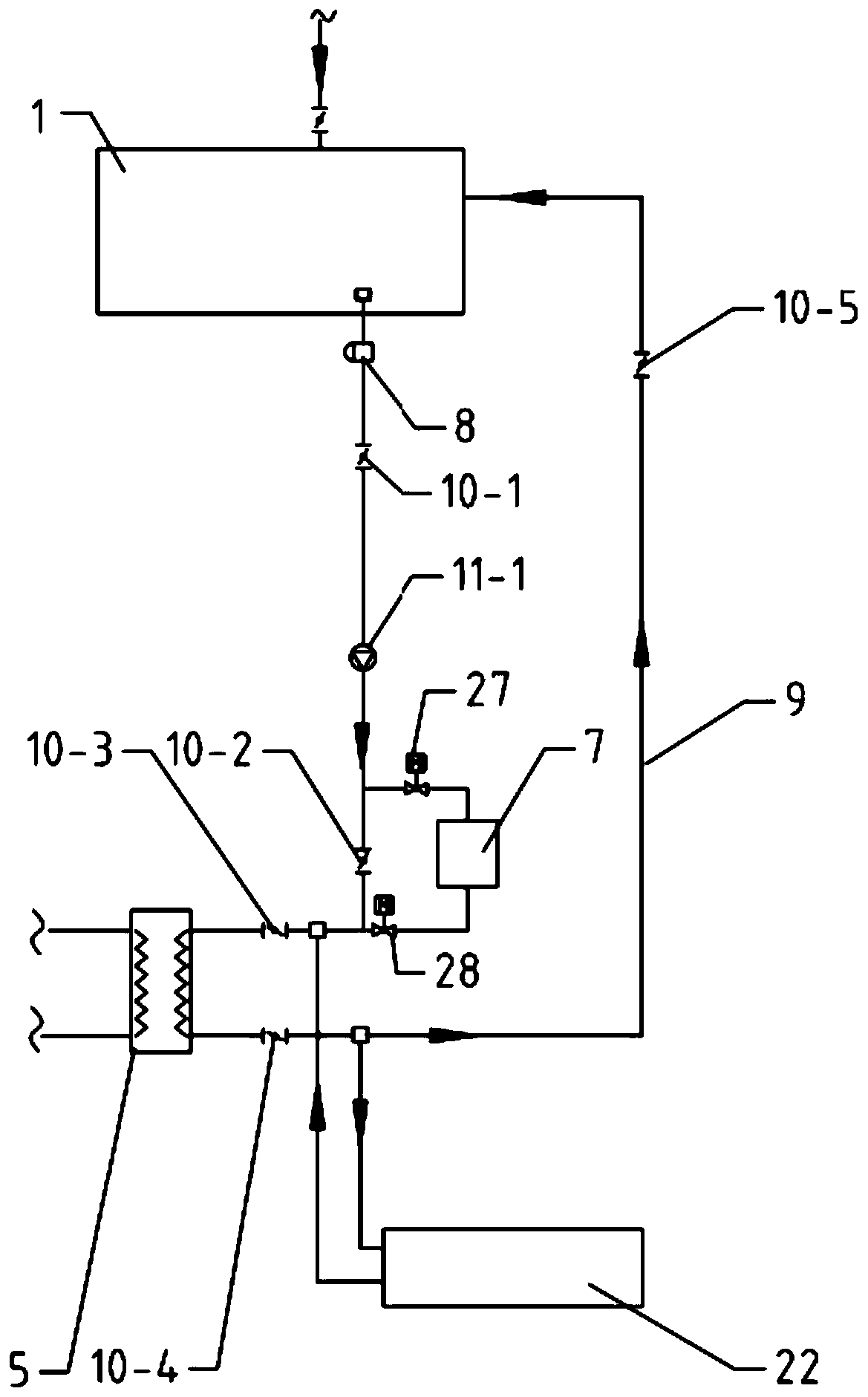
[0039] like Figure 1-4 As shown, a waste heat recovery and utilization system for an aquarium includes a seawater storage tank 1, a display tank 2, a sewage tank 3, a condenser 5, an evaporator 6, and a heating device 7. The seawater storage tank 1 and The display pool 2 is connected through a water pipe equipped with a first electromagnetic valve 10 and a first centrifugal pump 11, and the display pool 2 and the sewage pool 3 are connected through a water pipe equipped with a second centrifugal pump 29 and a second electromagnetic valve 26. like figure 2 As shown, the seawater storage tank 1 is connected with a first circulation branch 9, and the first circulation branch 9 is provided with a first pneumatic butterfly valve 10-1, a first water pump 11-1, and a second pneumatic butterfly valve in sequence. 10-2. The third pneumatic butterfly valve 10-3, the condenser 5, the fourth pneumatic butterfly valve 10-4, and the fifth pneumatic butterfly valve 10-5. Both the water in...

Embodiment 2

[0051] On the basis of Embodiment 1, the present invention also provides a working method for the waste heat recovery and utilization system of the aquarium, which includes the following steps:

[0052] S1: When the seawater in the display pool 2 needs to be replaced, manually turn on the second centrifugal pump 29 and the second solenoid valve 26 to pump the warm seawater in the display pool 2 into the sewage pool 3 for standby; Enter the seawater storage tank 1 for subsequent use.

[0053] S2: start the control system, when the second temperature detection device detects that the seawater temperature in the seawater storage tank 1 is lower than the set value, the PLC controller sends a driving signal to control the execution of the following work: first, open the first circulation branch 9 The first pneumatic butterfly valve 10-1, the second pneumatic butterfly valve 10-2, the third pneumatic butterfly valve 10-3, the fourth pneumatic butterfly valve 10-4, the fifth pneumati...

Embodiment 3

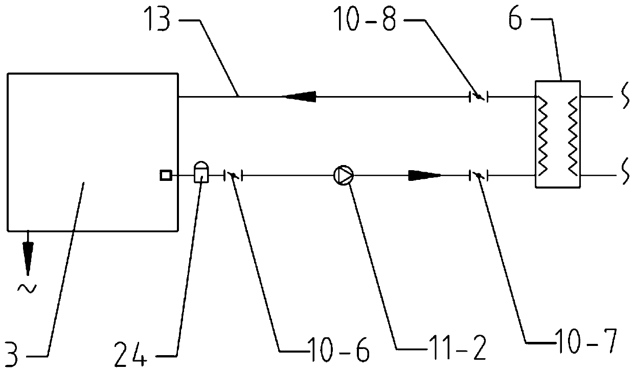
[0059] like Image 6 As shown, on the basis of embodiment 1, remove the filter screen of the rubber ball cleaning device 22, the water inlet filter screen of the first circulation branch 9 and the first sand tank filter 8, the water inlet of the second circulation branch 13 and the first The second sand tank filter 24 connects the water inlet and the water return port of the first circulation branch 9 through the heat dissipation coil 12 to form a closed circuit, the medium in the pipe is heat transfer oil, and the second circulation branch 13 The water inlet and the water return port are connected through the heat-absorbing coil 18 to form a closed circuit, and the medium in the pipe is heat-conducting oil. Wherein, the heat-resisting coil 12 and the heat-absorbing coil 18 are made of heat-resistant polyethylene, and in other embodiments, the material of the heat-dissipating coil 12 and the heat-absorbing coil 18 can also be made of triplicated polypropylene.

[0060] Absorb...


PUM


Abstract

The invention discloses a waste heat recycling system for an aquarium and a working method thereof, and belongs to the technical field of waste heat recycling. The system comprises a seawater storingpool, a showing pool, a wastewater pool, a condenser, an evaporator, a heating device and a control system. With the adoption of the system, waste heat in the wastewater can be recycled and supplied to seawater in the seawater storing pool and the showing pool; a plurality of heat supplying modes are combined; the energy is saved, and meanwhile, the water temperature meets the marine organism living standard; the water supplementing volume in the showing pool is metered through a flow meter, so that water is prevented from overflowing; a filtering device is additionally arranged at a circulating branch of the showing pool, and thus the seawater can be filtered while heat supplying, and as a result, the seawater use circle is prolonged; the water replacing frequency is reduced; the cost issaved; in addition, the temperature and level of water in the showing pool and the seawater storing pool can be detected in real time; and a driving signal sent by a PLC can be used for controlling related valves and pumps to open and close, and thus the temperature and level of water in the showing pool and the seawater storing pool can be automatically controlled.

Description

technical field [0001] The invention relates to the technical field of waste heat recovery and utilization, in particular to a waste heat recovery and utilization system for an aquarium. Background technique [0002] Marine life has high requirements on water quality and water temperature. During the operation and maintenance of the aquarium, various marine animal display pools need to change water regularly. The life support system of the aquarium refers to a set of equipment to maintain the survival of organisms and extend their lives. For the aquarium, the life support system is very important. Different marine organisms have different requirements for seawater temperature. Therefore, the life support systems of different aquariums in the aquarium need to be designed separately. Among them, the marine life display pools such as tropical fish and jellyfish need to be heated all year round. In order to maintain normal life, in the prior art, lithium bromide units or hot wat...

Claims


Application Information

Patent Timeline
Patent Type & Authority Applications(China)
IPC IPC(8): F24H4/02F24H9/00F24H9/18F24H9/20F28G1/12
CPCF24H4/02F24H9/0042F24H9/1818F24H9/2007F28G1/12
Inventor 冯其明徐焕勇闵向东王萌张国亮
Owner 青岛海田设计事务所有限公司
Why Eureka
Try Eureka