Flue gas denitration system

A flue gas and denitration technology, applied in the separation of dispersed particles, chemical instruments and methods, separation methods, etc., can solve problems such as increasing airflow resistance, reducing catalyst activity, explosion, etc., to prevent deformation of steel structures, ensure service life, The effect of preventing damage

Inactive Publication Date: 2019-08-23
无锡西江悦环境科技工程有限公司
View PDF7 Cites 5 Cited by
  • Summary
  • Abstract
  • Description
  • Claims
  • Application Information

AI Technical Summary

Problems solved by technology

[0005] The existing flue gas denitrification system has the following problems: 1. When the reactor is started in a cold state, the temperature of the catalyst module itself is very low. If ammonia is added at this time, a large amount of ammonium bisulfate will be generated and condensed in the pores of the catalyst , which greatly reduces the activity of the catalyst. If it is often operated in this way, the life of the catalyst module will be seriously reduced; 2. The entire reactor is made of steel structure, and there are many supporting beams and other facilities inside. If the temperature of the catalyst module rises too fast, it will cause internal and external Excessive temperature difference will also lead to deformation of the steel structure; 3. The temperature rise of the catalyst module exceeds the maximum allowable temperature rise, and the condensed water in the catalyst will evaporate suddenly, resulting in an explosion-like effect and damaging the catalyst structure. If the temperature difference between the inside and outside of the catalyst is too high 4. After a long time of use, there will be dust accumulation on the catalyst module in the reactor, which will increase the airflow resistance and affect the efficiency of the denitrification reaction

Method used


Image

  • Flue gas denitration system
  • Flue gas denitration system
  • Flue gas denitration system

Examples


Embodiment Construction

[0029] The specific implementation manners of the present invention will be further described below in conjunction with the drawings and examples. The following examples are only used to illustrate the technical solution of the present invention more clearly, but not to limit the protection scope of the present invention.

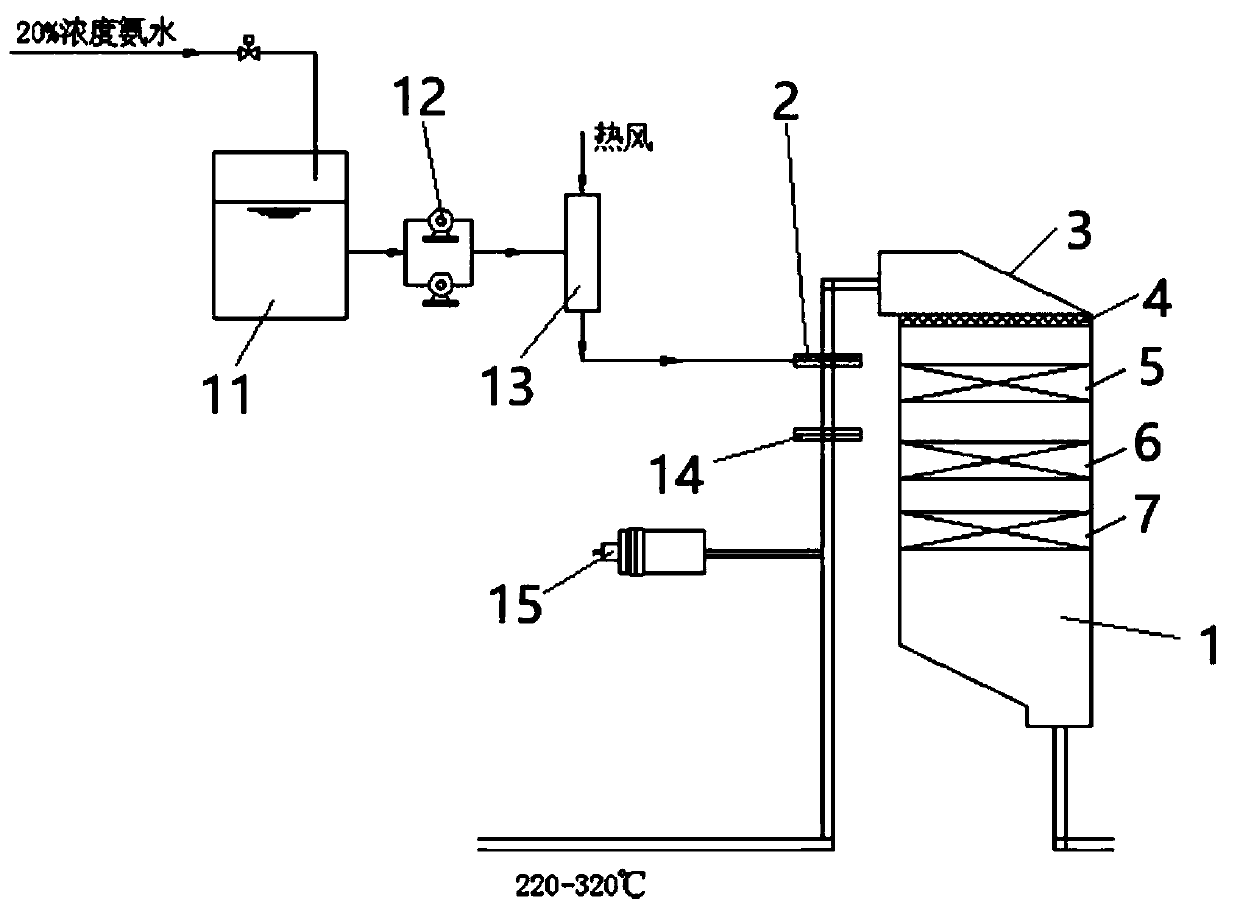
[0030] see figure 1 , the present invention relates to a flue gas denitrification system, which includes an ammonia water storage tank 11, an ammonia water delivery pump 12, an ammonia water evaporation tank 13, a tar adsorption device 14, a hot blast stove 15, an ammonia injection grid 2 and a reactor body 1;

[0031] Pass into the ammoniacal liquor of 20% concentration in the ammoniacal liquor storage tank 11, the outlet of ammoniacal liquor storage tank 11 is connected with the inlet of ammoniacal liquor delivery pump 12, the outlet of ammoniacal liquor delivery pump 12 is connected with the inlet of ammoniacal liquor evaporator 13, the outlet of ammonia...


PUM


Abstract

The invention relates to a flue gas denitration system. The system comprises an ammonia water storage tank, an ammonia water transfer pump, an ammonia water evaporation tank, a tar adsorption device,a hot-blast stove, an ammonia spray grille, a reactor body, a flow guiding plate, a rectifying grille, a first catalyst module, a second catalyst module, a spare catalyst module, a sonic soot blower and a compressor tank. The hot-blast stove provides hot air for the reactor body to preheat the catalyst modules, so the service life of the catalyst modules is ensured, a temperature difference between the inside and the outside of the reactor body is small, and deformation of a steel structure is prevented; the heating rate of the catalyst modules, the temperature difference between flue gas andthe catalyst modules and the heating rate of the flue gas are controlled to prevent the catalyst structure from being damaged; and ammonia gas and the flue gas are sufficiently and uniformly mixed bythe ammonia spray grille, and the catalyst modules are periodically purged and cleaned by the sonic soot blower, so the efficiency of a denitration reaction is ensured.

Description

technical field [0001] The invention relates to a flue gas denitrification system, in particular to a denitrification system for coke oven flue gas. It belongs to the technical field of flue gas treatment. Background technique [0002] The coking industry is an important part of the coal chemical industry. It is also an important upstream industry in the iron and steel industry. The extensive development has had a serious impact on the ecological environment. One of the sources of pollution, so controlling the emission of sulfur dioxide and nitrogen oxides is a major task facing the coking industry. [0003] At present, the main desulfurization process in my country is wet desulfurization, which mainly uses limestone, lime or sodium carbonate as detergents to wash the flue gas in the desulfurization tower to remove sulfur dioxide in the flue gas. [0004] The denitrification process mainly includes selective non-catalytic reduction (SNCR) process and selective catalytic re...

Claims


Application Information

Patent Timeline
Patent Type & Authority Applications(China)
IPC IPC(8): B01D53/90B01D53/56
CPCB01D53/8628B01D53/90
Inventor 朱国刚朱晨辰
Owner 无锡西江悦环境科技工程有限公司
Why Eureka
Try Eureka