Combined osmotic and hydrogel cervical dilators and method of making same

A dilator and hydrogel technology, applied in the field of cervical dilators, can solve the problems of irregular dry stem shape and geometry, low mechanical strength, slow hydration, etc.

Pending Publication Date: 2019-08-27
MEDICEM TECH SRO
View PDF33 Cites 1 Cited by
  • Summary
  • Abstract
  • Description
  • Claims
  • Application Information

AI Technical Summary

Problems solved by technology

However, dilators from LJ have various disadvantages: hydration is relatively slow and rather irregular, dry stems are rather irregular in morphology and geometry, osmotic pressure is relatively low, mechanical dilation resists pressure from stiff cervical tissue (e.g., Internal os) will be limited, mechanical strength at maximum hydration may be too low to prevent disintegration, sterilization of the product may be indeterminate, and have no design features or properties to prevent multiple uses to reduce the risk of infection

Method used


Image

  • Combined osmotic and hydrogel cervical dilators and method of making same
  • Combined osmotic and hydrogel cervical dilators and method of making same

Examples


Embodiment 1

[0055] Hydrogels for cervical dilators were prepared according to US Patent 6,232,406, which is incorporated by reference in its entirety. PAN having a weight average molecular weight of 200,000 g / mol was dissolved in a 55% by weight NaSCN aqueous solution to form a 10% by weight polymer solution. NaOH dissolved in 55% by weight aqueous NaSCN solution was added at ambient temperature in the amount required to obtain a PAN / NaOH mass ratio of 1:10. The solution was then transferred to a jacketed tubular reactor where it was heated to 70°C for 60 hours. The resulting multi-block acrylic copolymer solution was cooled to 40°C and transferred to a pressure vessel, which was then fed by pressurized gas into a metering pump with a progressing cavity rotor. The solution is extruded through a cooling nozzle into a coagulation bath filled with an aqueous NaSCN solution having a NaSCN concentration of 1 to 5% by weight. The coagulated hydrogel sticks were washed until substantially all ...

Embodiment 2

[0061] The hydrogel prepared according to Example 1 was soaked with an aqueous solution of 10% by weight of the following monomers:

[0062] 1. Sodium acrylate

[0063] 2. Methacryloxypropane-1-sulfonic acid

[0064] 3.4-Vinylphenylsulfuric acid

[0065] 4. Vinylphosphonic acid.

[0066] After each solution reached equilibrium, the monomer-soaked hydrogel sticks were stretched on a drying rack similarly to Example 1, and dried at 80 °C for 18 h. Although no initiator was used and drying was performed in the presence of air, all monomers polymerized and formed an interpenetrating network of polyelectrolytes within the multi-block copolymer hydrogel. When swollen in isotonic solution, no elution of the polyelectrolyte was observed because it was apparently firmly anchored within the hydrogel structure.

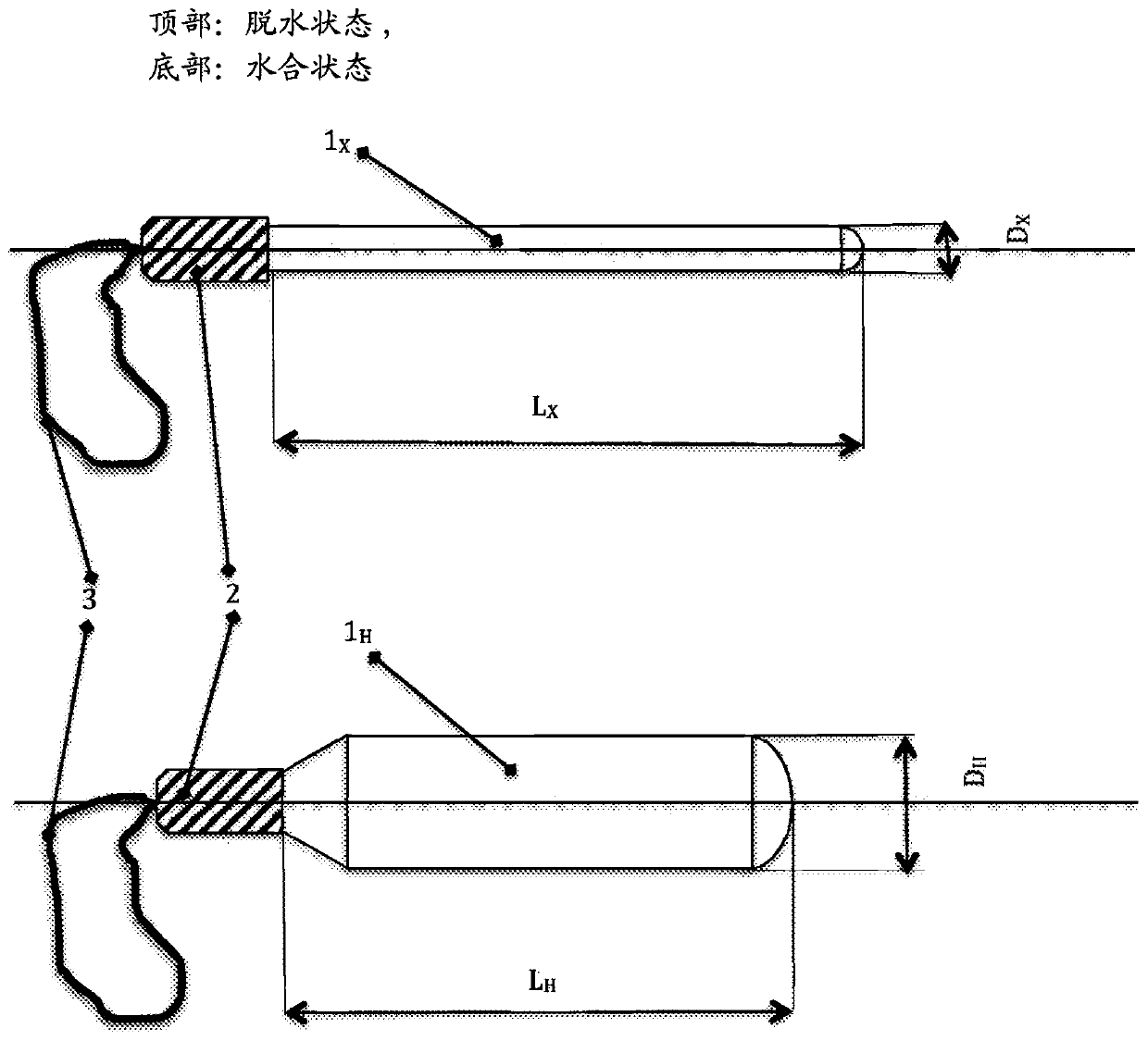
[0067] The xerogel stem can then be equipped with a glued plastic handle and sterilized by radiation or gas. figure 2 A cervical dilator is shown in a dehydrated state (up...

Embodiment 3

[0070] The hydrogel interpenetrating network of Example 2 with poly(methacryloxypropane-1-sulfonic acid) monomer was treated with an excess of 5% by weight sodium sulfate, 3% by weight 1,2-propylene glycol and 1 Soak in an aqueous solution of wt% triethanolamine. Then, it was dried under radial tension at 70° C. until a residual water content of about 18% by weight was reached. The product is then cut to size, trimmed, fitted with a handle and sealed in a sterilization bag, as in the previous embodiment. The cervical dilator device was sterilized by electron beam at 40 kGy. This cervical dilator device provides rapid cervical ripening, has strong radial dilation and can be shaped to fit any specific endocervical canal geometry prior to insertion.


PUM

PropertyMeasurementUnit
diameteraaaaaaaaaa
lengthaaaaaaaaaa

Abstract

A cervical dilator including a stem comprising a partly or fully dehydrated hydrogel comprising a water-insoluble synthetic hydrophilic polymer capable of radial expansion due to absorption of water from a bodily fluid. The cervical dilator softens and ripens the cervical tissue and expands the cervical canal by a combined action of radial hydrogel stem expansion and osmotic withdrawal of water from the tissue. The osmotic withdrawal is caused by at least one osmotically active compound, such as a water-soluble salt, a polyelectrolyte, or a mixture thereof, wherein the at least one osmoticallyactive compound is dispersed in the hydrogel. The cervical dilator may also include a non-toxic plasticizer of the hydrogel, such as water.

Description

[0001] Cross References to Related Applications [0002] This application claims priority to U.S. Provisional Patent Application No. 62 / 404,997, filed October 6, 2016. The disclosure of which is incorporated herein by reference. technical field [0003] The present invention relates to cervical dilators, and methods of making cervical dilators. Background technique [0004] Tissue expansion is used in various surgical procedures. Tissue expansion can be temporary or permanent. A well-known example of temporary dilation is dilation of the gynecological endocervix. It occurs naturally during childbirth, but can also be achieved artificially in various ways, for example by administering prostaglandins (see MJ Keirse, Prostaglandins in preinduction cervical ripening. Meta-analysis of worldwide clinical experience, The Journal of reproductive medicine (1993) 38: 89-100). Using mechanical dilators, the cervical canal can also temporarily dilate in response to short-term radia...

Claims


Application Information

Patent Timeline
Patent Type & Authority Applications(China)
IPC IPC(8): A61M29/02A61L31/14A61K9/00
CPCA61L31/145A61M29/02A61L31/14A61B2017/00893A61B2017/00898A61B2017/00942A61B2017/4225A61P15/00A61B17/42A61B90/02A61M2210/1433B29C55/005B29C37/0092A61M2207/00A61M2205/0216A61B17/00
Inventor V.斯托伊T.德鲁内基M.杜迪克P.斯特利切克Z.沃科诺瓦
Owner MEDICEM TECH SRO
Why Eureka
Try Eureka