MVR coupled heat pump evaporative concentration system and evaporative concentration method

An evaporation concentration system, coupled heat pump technology, applied in the field of energy saving and environmental protection, can solve the problems of difficulty in increasing equipment operation, small application range, complicated distillation operation, etc., achieve full utilization of waste heat, reduce the size of heat exchange equipment, improve The effect of work efficiency

Active Publication Date: 2021-08-03
SHANDONG UNIV OF TECH
View PDF8 Cites 0 Cited by
  • Summary
  • Abstract
  • Description
  • Claims
  • Application Information

AI Technical Summary

Problems solved by technology

The main reasons for these additional energy consumption are the low thermal power conversion efficiency of the compressor, the equipment not working at the optimum efficiency, and the insufficient utilization of MVR waste heat, etc.
[0004] At present, there are many studies on MVR technology. For example, Chinese patent CN106237643A discloses a kind of MVR heat pump rectification system, which can effectively utilize the latent heat of distillation tower top steam and tower still liquid, and save the operation cost of rectification tower; but the system It makes the rectification operation complicated, and the application range is small, and it can only be used when the temperature difference between the top and the bottom of the tower is less than 10°C
Chinese patent CN106068149A discloses a double-effect cross-flow MVR evaporation and concentration system, which can effectively improve the energy efficiency of MVR, but increases the difficulty of equipment operation, and does not recover low-quality energy in MVR condensate and concentrate

Method used


Image

  • MVR coupled heat pump evaporative concentration system and evaporative concentration method
  • MVR coupled heat pump evaporative concentration system and evaporative concentration method
  • MVR coupled heat pump evaporative concentration system and evaporative concentration method

Examples


Embodiment 1

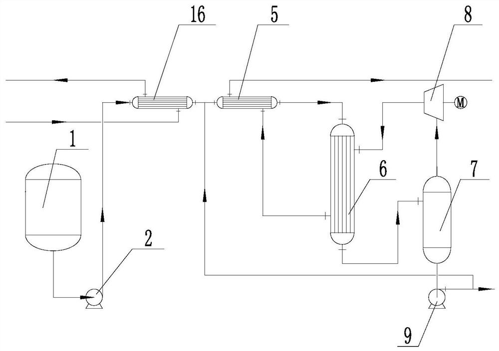
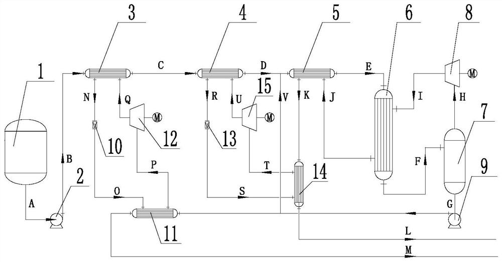
[0042] Such as figure 2 As shown, the MVR coupling heat pump evaporation and concentration system includes the MVR system and the heat pump system. The MVR system specifically includes the raw material tank, the feed pump, the MVR waste heat recovery device, the MVR evaporator, the MVR two-phase separator, the MVR compressor and the reflux extraction pump. The heat pump system specifically includes a primary preheater, a primary throttling and pressure reducing valve, a primary compressor, a primary low temperature heat exchanger, a secondary preheater, a secondary throttling and pressure reducing valve, a secondary compressor and Two-stage low-temperature heat exchanger; raw material tank, feed pump, primary preheater, secondary preheater, MVR waste heat recovery device, MVR evaporator, MVR two-phase separator and MVR compressor are connected in sequence, MVR evaporator It is connected to the MVR compressor, the MVR two-phase separator is connected to the reflux extraction p...

Embodiment 2

[0052] The MVR coupling heat pump evaporative concentration system and the evaporative concentration method are the same as in Example 1.

[0053] Wastewater containing 5w% NaCl at 10000kg / h enters the MVR system at 25°C. After being preheated by the primary preheater, the temperature is 62°C. After being preheated by the secondary preheater, the temperature is 81°C. In the MVR evaporator 77 Evaporation is carried out at ℃, the evaporation rate is 50%, the MVR compressor is a Roots compressor, and the working compression ratio is 1.4. The Roots compressor uses frequency conversion to adjust the speed, and the working medium is chlorofluorocarbon (R152A). After the condensed water leaves the MVR waste heat recovery device, the temperature of the condensed water is 84°C, and after passing through the secondary low-temperature heat exchanger, the temperature of the low-temperature condensed water reaches 57.7°C. After the concentrated liquid leaves the MVR two-phase separator, t...

Embodiment 3

[0058] The MVR coupling heat pump evaporative concentration system and the evaporative concentration method are the same as in Example 1.

[0059] Wastewater containing 5w% NaCl at 1000kg / h enters the MVR system at 25°C. After being preheated by the primary preheater, the temperature is 60°C. After being preheated by the secondary preheater, the temperature is 78.64°C. Evaporation is carried out at ℃, the evaporation rate is 40%, the MVR compressor is a Roots compressor, and the working compression ratio is 1.4. Roots compressor frequency conversion to adjust the speed. The working medium of the first heat pump group is liquid ammonia, and the working medium of the second heat pump group is chlorofluorocarbon (R152A). After the condensed water leaves the MVR waste heat recovery device, the temperature of the condensed water is 91°C, and after passing through the secondary low-temperature heat exchanger, the temperature of the low-temperature condensed water reaches 68°C. Aft...


PUM


Abstract

The invention belongs to the technical field of energy saving and environmental protection, and in particular relates to an MVR coupling heat pump evaporation concentration system and an evaporation concentration method. The MVR coupling heat pump evaporation and concentration system includes the MVR system. The MVR system includes the raw material tank, the raw material preheater, the MVR waste heat recovery device, the MVR evaporator and the MVR two-phase separator. The heat pump system is used instead of the raw material preheater. The heat pump system Coupling between raw material tank and MVR waste heat recovery device. In the present invention, the logistics leaving the system undergoes sufficient heat exchange, recovering waste heat in the logistics as much as possible, and improving the energy utilization rate of the coupling system.

Description

technical field [0001] The invention belongs to the technical field of energy saving and environmental protection, and in particular relates to an MVR coupled heat pump evaporation and concentration system and an evaporation and concentration method. Background technique [0002] Mechanical Vapor Recompression (MVR, Mechanical Vapor Recompression) technology is an important energy-saving technology for evaporation. It increases the temperature of steam through mechanical compression equipment and uses it to heat raw materials, which can effectively reduce evaporation energy consumption and cooling water consumption. It is widely used in Food processing, waste water recycling, concentrated crystallization and other fields. [0003] Existing MVR evaporation system ( figure 1 ), usually with feeding, preheating, MVR evaporation, condensate discharge, dope discharge (crystallization) and other systems. The waste water is extracted from the raw material tank through the feed pu...

Claims


Application Information

Patent Timeline
Patent Type & Authority Patents(China)
IPC IPC(8): B01D1/28B01D1/00C02F1/04F25B30/02F25B27/02
CPCB01D1/0011B01D1/28C02F1/041C02F1/043C02F1/048F25B27/02F25B30/02Y02P70/10Y02A30/274
Inventor 庄淑娟宋峰崔洪友孙秀玉解玉娇付强王鸣
Owner SHANDONG UNIV OF TECH
Why Eureka
Try Eureka