
Oil sludge resource utilization system and technology

A technology for resource utilization and sludge, applied in the petroleum industry, chemical instruments and methods, water/sludge/sewage treatment, etc., can solve the problems of large equipment investment, secondary pollution, complex system, etc., and achieve complete extraction and avoid burning. , The effect of uniform and rapid heating

Inactive Publication Date: 2019-09-03
上海恒埠环保科技有限公司
View PDF11 Cites 2 Cited by
  • Summary
  • Abstract
  • Description
  • Claims
  • Application Information

AI Technical Summary

Problems solved by technology

Chinese patent 201110082159.9 discloses an integrated method and system for pyrolysis of oily sludge to regenerate fuel oil. It uses a circulating fluidized bed to burn coal and pyrolysis slag to provide energy for pyrolysis. The pyrolysis slag contains heavy metals, which is easy to bring Secondary pollution, there are problems such as complex system and large investment in equipment

Method used


Image

  • Oil sludge resource utilization system and technology
  • Oil sludge resource utilization system and technology
  • Oil sludge resource utilization system and technology

Examples


Embodiment 1

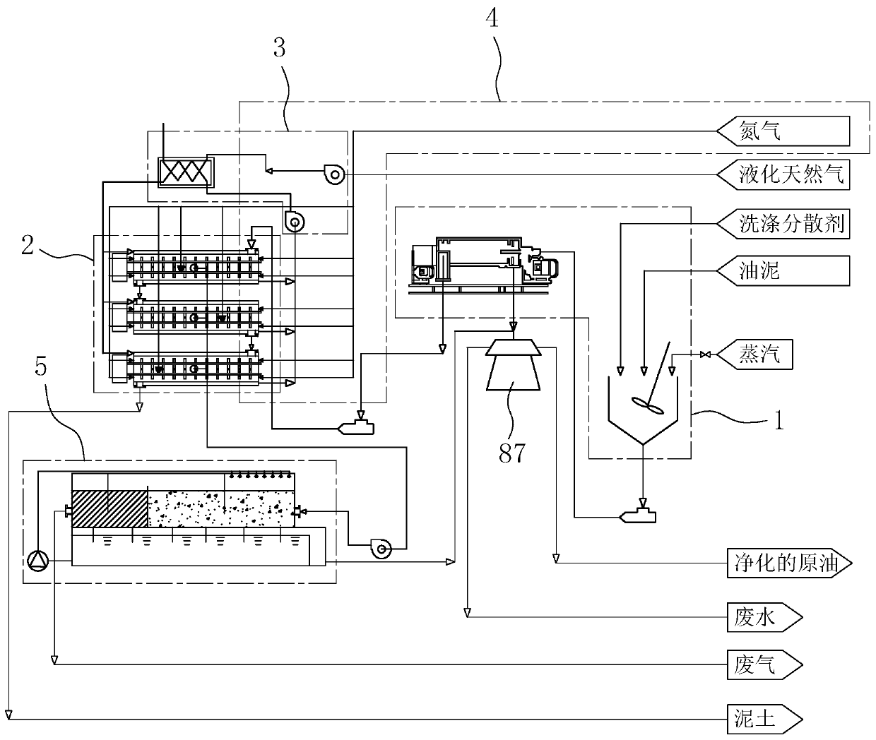
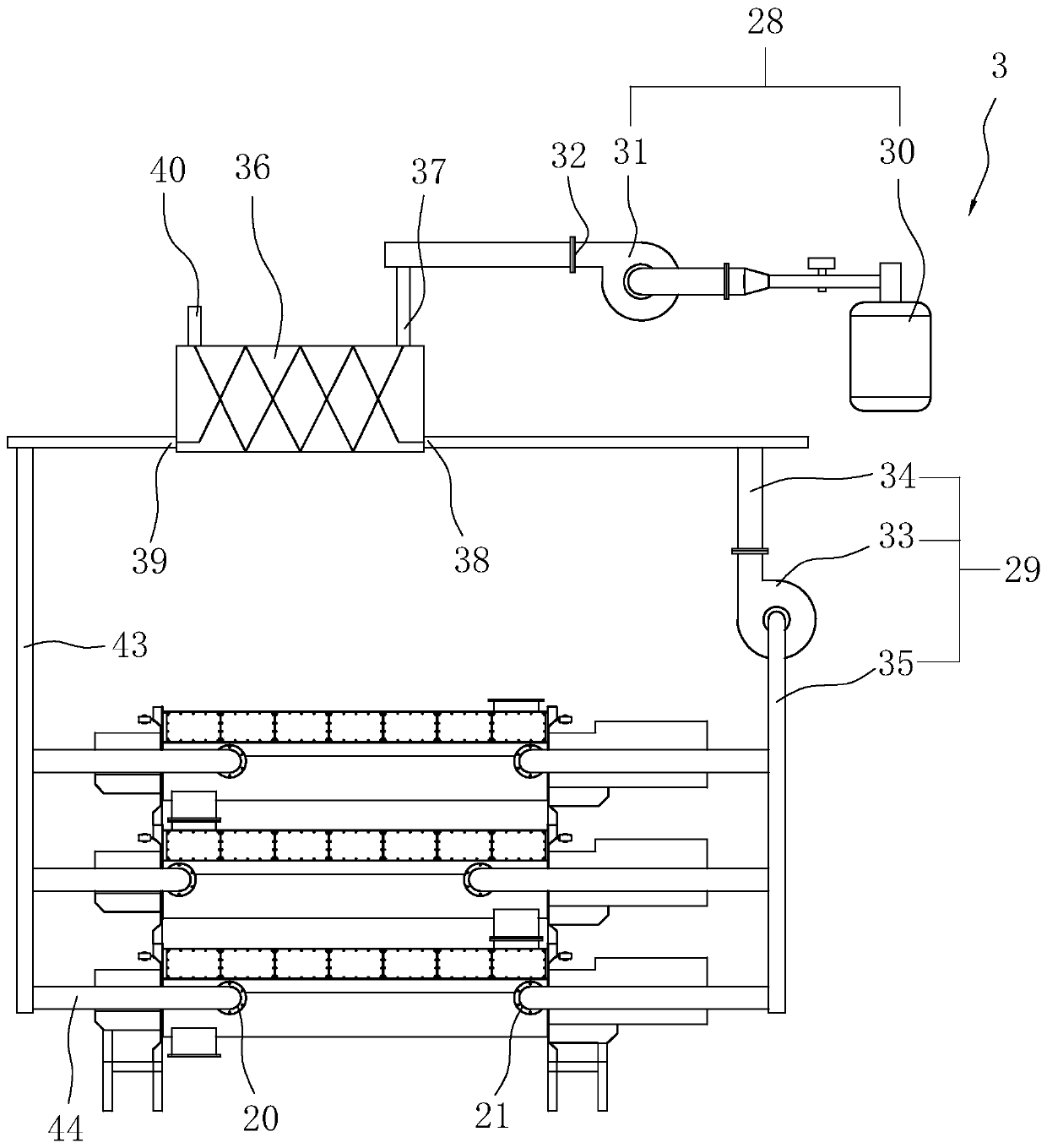
[0056] refer to figure 1 , an oil sludge resource utilization system, comprising an oil sludge preliminary separation system 1, a pyrolysis system 2, a heating system 3, an explosion-proof system 4, a condensation system 5, and an oil-water separation device 87; the oil sludge initial separation system 1 is used for the liquid-containing phase Preliminary treatment of more oil sludge to separate the liquid phase that is relatively easy to separate in the oil sludge; pyrolysis system 2 is used to fully pyrolyze the oil sludge, so as to separate the water, oil and solid phase in the oil sludge to achieve the purpose of fully pyrolyzing the oil sludge; the heat supply system 3 is used to supply heat to the pyrolysis system 2, so that the oil sludge in the pyrolysis system 2 can be kept at a temperature of about 500 ° C, so that the crude oil and water in the oil sludge It is decomposed in the form of gas phase; the explosion-proof system 4 is used to fill the pyrolysis system 2 w...

Embodiment 2

[0076] refer to Figure 12 , an oil sludge resource utilization process, comprising the following steps:

[0077] Step 1, pretreatment of oil sludge, first put the oil sludge into the oil sludge washing tank 9 in Example 1, and add washing and dispersing agent to the oil sludge, and pass high-temperature steam into the oil sludge, while using the oil sludge in Example 1 The stirring blade 10 stirs the sludge;

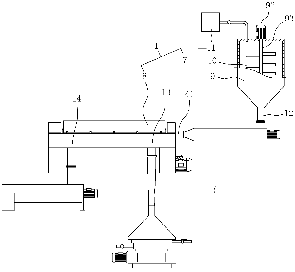
[0078] Step 2: Preliminary solid-liquid separation, adding the oil sludge obtained in step 1 to the decanter centrifuge 8 for solid-liquid separation to obtain solid phase oil sludge and liquid phase oil-water mixture; the decanter centrifuge 8 is preferably Shanghai Ruiwei The sludge wastewater treatment centrifuge produced by Electromechanical Equipment Co., Ltd. is LW420X1800Y. The decanter centrifuge 8 is provided with a first liquid phase outlet 13 and a first solid phase outlet 14, and the solid phase sludge is discharged from the first solid phase outlet 14. , ...


PUM


Abstract

The invention discloses an oil sludge resource utilization system and technology, and applications in the technical field of oil sludge pyrolysis resource utilization. The technology is capable of solving problems in the prior art that pyrolysis residue contains heavy metals, secondary pollution is easily caused, system is complex, and equipment investment is high in conventional pyrolysis method.The oil sludge resource utilization system comprises a pyrolysis system used for pyrolysis of oil sludge, a heat supply system used for supplying the pyrolysis system with heat, an explosion-proof system used for avoiding crude oil combustion or explosion, and a condensation system. The technical effects are that: the heat supply system and the pyrolysis system are arranged independently, contactof open fire with oil sludge is avoided, and the whole housing is protected with nitrogen gas, so that pyrolysis is safer, and generation of harmful gas such as dioxins is avoided; a high efficiencyheat exchanger is adopted for heat conduction, and physical condensation is adopted by the condensation system, so that pyrolysis and condensation efficiency is higher, and more energy is saved.

Description

technical field [0001] The invention relates to the technical field of oil sludge pyrolysis resource utilization, in particular to an oil sludge resource utilization system and process. Background technique [0002] In the process of mining, transporting and processing petroleum in the petrochemical industry, a large amount of sludge will be produced. According to data, the annual output of oil sludge produced in the process of oil exploitation in my country has exceeded one million tons. These sludges are difficult to settle and contain a large amount of metal pollutants. If they are discharged directly, they will pollute land and water resources. With the overall improvement of my country's environmental protection awareness and the improvement of my country's environmental protection laws and regulations, the treatment technology of oil sludge has become a hot issue in the field of energy and environmental science. [0003] At present, the treatment technologies of oily...

Claims


Application Information

Patent Timeline
Patent Type & Authority Applications(China)
IPC IPC(8): C02F11/18C02F11/13C10G1/00C02F103/36
CPCC02F11/18C02F2103/365C02F2303/26C10G1/002C02F11/13
Inventor 王亚洲
Owner 上海恒埠环保科技有限公司
Learn More