Oil-water separator and separation system

A technology of oil-water separator and separation channel, applied in liquid separation, separation method, immiscible liquid separation, etc., to achieve the effect of convenient automatic control, high-efficiency oil-water separation effect, and acceleration of oil-water separation speed

Pending Publication Date: 2019-09-10
INST OF PROCESS ENG CHINESE ACAD OF SCI
View PDF9 Cites 7 Cited by
  • Summary
  • Abstract
  • Description
  • Claims
  • Application Information

AI Technical Summary

Problems solved by technology

[0013] The purpose of the present invention is to solve the problem of oil-water separation in the existing chemical automation production process, especially the shortcomings in the MMA preparation process, and propose a high-efficiency oil-water separator for chemical industry

Method used


Image

  • Oil-water separator and separation system
  • Oil-water separator and separation system
  • Oil-water separator and separation system

Examples


Embodiment 1

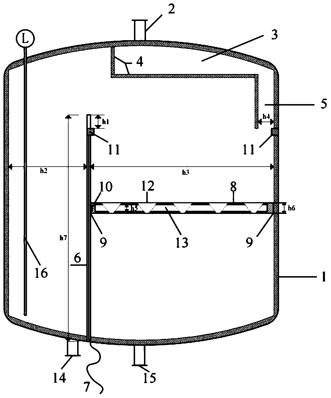
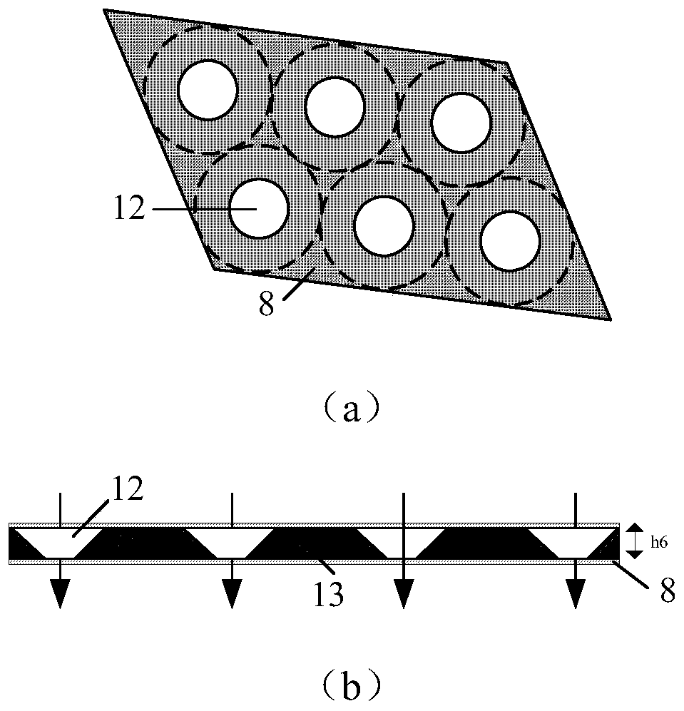
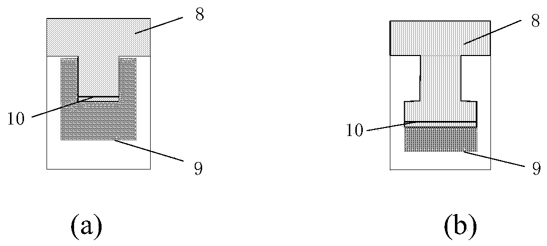
[0037] This embodiment provides an oil-water separator, such as figure 1 and 2 As shown, it includes 1 oil-water separator tank, 2 feed inlet, 3 separation channel, 4 hydrophobic membrane, 5 downcomer, 6 physical partition, 7 magnetic induction signal device, 8 liquid level floating plate, 9 groove guide rail , 10 magnetic induction end, 11 limit block, 12 liquid level floating plate groove, 13 air bag, 14 oil outlet, 15 water outlet. In particular, a layer of hydrophobic membrane 4 is coated on the inner wall of the separation channel, which can improve the efficiency of oil-water separation; at the same time, a physical partition 6 is connected to the bottom of the oil-water separator tank, and a magnetic induction liquid level signal device is arranged in the physical partition 6 7. The liquid level in the water phase area can be connected to the physical partition 6 through the magnetic induction terminal 10 at the end of the liquid level floating plate 8, so that real-ti...

Embodiment 2

[0039] This embodiment provides an oil-water separation system, such as image 3 As shown, it includes 16 oil phase liquid level monitoring instruments, 17 feed control valves, 18 water outlet control valves, 19 oil outlet control valves, and 20 water level monitoring instruments.

[0040] The mixed solution containing MMA and water enters the oil-water separator 16 through the feed regulating valve 17 on the feed pipeline, realizes the separation of MMA and water in the oil-water separator 16, controls the water phase recovery rate by the water outlet regulating valve 18, and passes The oil discharge control valve 19 regulates the recovery rate of MMA.

[0041] During the process of separating MMA and water, MMA and water are separated in the oil-water separator 16 . When the liquid level of the water phase in the oil-water separator 16 is high, the water level monitoring instrument 20 is used to increase the opening of the water control valve 18 to increase the recovery rat...

Embodiment 3

[0043] The present embodiment provides a kind of utilizing the oil-water separator of embodiment 1 to separate MMA and water mixture, and the characteristic parameter of oil-water separation tank mainly is: 1) feed inlet diameter is 25mm, and the diameter of separation channel is described feed inlet diameter 2) The diameter of the oil-water separation tank is 800mm, and the diameter of the liquid level floating plate h3 is 480mm; 3) The height of the oil-water separation tank is 1800mm, and the height of the physical partition h7 is 1080mm. The liquid level floating plate 8 is a hollow structure filled with air. According to the density difference between MMA (density 0.94g / ml) and water (density 1.0g / ml), the density of the liquid level floating plate is adjusted to 0.97g / ml. Make it at the separation interface of the water phase area and the mixed phase area, and can accurately indicate the liquid level of the water phase area.

[0044] Liquid level floating plate grooves 1...


PUM


Abstract

The invention discloses an oil-water separator for chemical industry and an oil-water separation system. The oil-water separator is of a tank-type hollow structure and is internally provided with a separation channel coated with a hydrophobic membrane, a physical partition plate and a novel liquid level floating plate; and an oil phase discharging hole and a water phase discharging hole are respectively formed in a tank bottom. Due to the arrangement of a hydrophobic membrane layer, the rapid separation of oil and water is realized in the separation channel, and the oil-water separation time is shortened; the density-adjustable oil-water separation liquid level floating plate is designed by adopting a novel air sac floating plate, so that the separation of an oil phase and a water phase isefficiently accelerated; and meanwhile, due to the adoption of a magnetic induction device at a liquid level floating plate end, phase interface positions of the two phases including the oil phase and the water phase can be monitored in real time, the yield of the water phase is directed to be controlled, an effective liquid level monitoring means is provided for a chemical oil-water separation process, and the oil-water separator is suitable for traditional chemical oil-water separation controlled a DCS.

Description

technical field [0001] The invention belongs to the technical field of chemical oil-water separation process, and in particular relates to a high-efficiency oil-water separator and a separation system for chemical industry. Background technique [0002] Methyl methacrylate (MMA) is an important chemical raw material and one of the top ten chemical products with the highest dependence on imports in China. MMA is mainly used in the production of polymethyl methacrylate (PMMA), which can be copolymerized with methacrylate, acrylate, butadiene, acrylonitrile, styrene and other monomers to produce coatings, acrylic fibers, adhesives, Printing and dyeing agents, lubricating oil additives and other products; at the same time, MMA can also be used as a cross-linking agent, modifier and unsaturated polyester, rubber and functional latex to further copolymerize to produce other high-energy polymer materials. MMA is soluble in various organic solvents such as ethanol, ether, acetone, ...

Claims


Application Information

Patent Timeline
Patent Type & Authority Applications(China)
IPC IPC(8): B01D17/028B01D17/022
CPCB01D17/02B01D17/0211
Inventor 张锁江张军平陈嵩嵩苏航张国帅张凯亮
Owner INST OF PROCESS ENG CHINESE ACAD OF SCI
Why Eureka
Try Eureka