Thin film deposition device and method adopting controllable magnetic field for screening laser plasma

A magnetic field screening and plasma technology, applied in ion implantation plating, metal material coating process, coating, etc., can solve the problem of different power density, smaller incident laser energy, composition of laser plasma plume, ion valence and Kinetic energy differences and other issues can be improved to improve quality and stability, facilitate equipment operation, and ensure consistency

Inactive Publication Date: 2019-10-11
ARMY ENG UNIV OF PLA
View PDF4 Cites 2 Cited by
  • Summary
  • Abstract
  • Description
  • Claims
  • Application Information

AI Technical Summary

Problems solved by technology

However, the above-mentioned patents and documents only studied the influence of magnetic field on the properties of laser plasma deposited films, but failed to solve the problem of large particles and droplets in laser plasma
[0004] Secondly, in the process of laser deposition of thin films, the size of the focused spot changes due to the uneven ablation of the target surface, and the continuous pollution of the laser incident window by the sputtered laser plasma causes the incident laser energy to become smaller. When the power density of the laser ablation target is different, the composition, ion valence state and kinetic energy of the generated laser plasma plume are different, so the stability of the deposited film performance cannot be guaranteed.
In response to this problem, Chinese patent CN108950485A discloses a coating control method and system for pulsed laser deposition equipment and pulsed laser deposition equipment. Laser deposition is judged by real-time collection of laser plasma plume images and matching with corresponding preset standard data. Whether the film process is normal, so as to control the stability of the laser deposited film, but this method and equipment cannot solve the problem of large particles in the laser plasma

Method used


Image

  • Thin film deposition device and method adopting controllable magnetic field for screening laser plasma
  • Thin film deposition device and method adopting controllable magnetic field for screening laser plasma
  • Thin film deposition device and method adopting controllable magnetic field for screening laser plasma

Examples


Embodiment 1

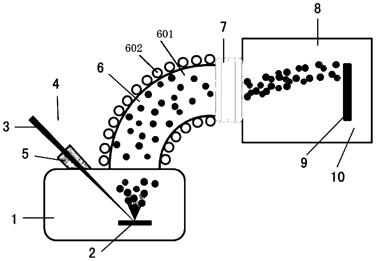
[0031] A film deposition device for screening laser plasma with a controllable magnetic field, comprising a laser plasma cavity 1, a laser incident window 5 is arranged on the laser plasma cavity 1, and a laser beam 3 enters the laser plasma cavity 1 through a focusing lens 4 and a laser incident window 5 The target material 2 placed on the target support, the laser plasma chamber 1 is connected to one end of the magnetic filter elbow 6 through a flange, the other end of the magnetic filter elbow 6 is connected to one end of the focusing magnetic field tube 7 through a flange, and the focusing magnetic field tube 7 is connected to the other end. One end is connected to the film deposition chamber 8 through a flange, and a substrate table 9 is arranged in the film deposition chamber 8, and a substrate is arranged on the substrate table 9.

[0032] A negative bias device 10 for applying a negative bias to the substrate table 9 is also provided in the film deposition chamber 8 . ...

Embodiment 2

[0036] A film deposition method for screening laser plasma with a controllable magnetic field, using a film deposition device for screening laser plasma with a controllable magnetic field described in Example 1, comprising the following steps:

[0037] Step 1, cleaning the substrate and fixing it on the substrate table 9 in the film deposition chamber 8;

[0038] Step 2, vacuuming the laser plasma chamber 1, the magnetic filter elbow 6, the focusing magnetic field cylinder 7 and the film deposition chamber 8;

[0039] Step 3, using an ion source to clean the coating surface of the substrate to remove oil and impurities absorbed by the coating surface of the substrate.

[0040] Step 4, introducing the laser beam 3 into the laser plasma cavity 1 through the laser incident window 5 . Adjust the distance from the focusing lens 4 to the target 2 by moving back and forth, focus the laser beam 3 on the surface of the target 2, and use the focused laser beam 3 to ablate the surface o...

Embodiment 3

[0050] A method for depositing a tetrahedral amorphous carbon film with a controllable magnetic field screening laser plasma, using a thin film deposition device for screening laser plasma with a controllable magnetic field described in Example 1, comprising the following steps:

[0051] Step 1. Fix the silicon wafer substrate with a diameter of 200mm on the substrate table in the thin film deposition chamber 8 after wiping with alcohol ether mixture and ultrasonic vibration cleaning.

[0052] Step 2: Close the doors of the laser plasma chamber 1 and the film deposition chamber 8, and start vacuuming the laser plasma chamber 1, the magnetic filter elbow 6, the focusing magnetic field cylinder 7 and the film deposition chamber 8.

[0053] Step 3. When the vacuum is pumped to 1×10 -5 Pa, use the ion source to clean the coating surface of the silicon wafer substrate for 10 minutes to remove the oil stains and impurities absorbed on the surface.

[0054] Step 4, using a KrF excim...


PUM


Abstract

The invention discloses a thin film deposition device adopting a controllable magnetic field for screening laser plasma. The thin film deposition device comprises a laser plasma cavity, a target support and a target material, wherein the target support and the target material are arranged in the laser plasma cavity, the laser plasma cavity is connected with a focusing magnetic field cylinder through a magnetic filtering elbow, the focusing magnetic field cylinder is connected with a thin film deposition cavity, a substrate table and a substrate are arranged in the thin film deposition cavity,and the magnetic filtering elbow comprises an elbow and a conductive coil wound around the elbow. A thin film precipitation method through screening the laser plasma by the controllable magnetic fieldis further disclosed. The device and method is convenient to operate, simple in process, strong in laser plasma controllability and capable of preparing a high-quality nano-film material, and has practical application value.

Description

technical field [0001] The invention belongs to the field of laser deposition thin film materials, in particular to a thin film deposition device for screening laser plasma with a controllable magnetic field, and also relates to a thin film deposition method for screening laser plasma with a controllable magnetic field. Background technique [0002] The laser deposition method is a new thin film preparation technology developed in the 1980s. It uses a high-energy laser to focus and ablate the surface of the target, so that the target is locally heated instantaneously to generate high-temperature and high-pressure plasma. Thin films are emitted onto the substrate opposite the target. Compared with other thin film preparation technologies, laser deposition has the advantages of low temperature deposition, high energy coupling efficiency, easy control, and the ability to prepare multi-component composite thin films, etc., and has broad application prospects. However, the curre...

Claims


Application Information

Patent Timeline
Patent Type & Authority Applications(China)
IPC IPC(8): C23C14/28
CPCC23C14/28
Inventor 程勇黄国俊陆益敏万强韦尚方米朝伟田方涛王赛
Owner ARMY ENG UNIV OF PLA
Why Eureka
Try Eureka