
High-salt wastewater salt separation system and process

A high-salt wastewater and salt separation technology, which is applied in the direction of alkali metal sulfite/sulfite, water/sewage treatment, water/sludge/sewage treatment, etc., can solve the problem of unsatisfactory natural evaporation effect and difficult to achieve production Standards, reducing the economic benefits of enterprises and other issues, to achieve the effect of reducing the content of sulfate ions, avoiding damage, reducing investment costs and energy consumption

Pending Publication Date: 2019-10-18
内蒙古晶泰环境科技有限责任公司 +1
View PDF4 Cites 7 Cited by
  • Summary
  • Abstract
  • Description
  • Claims
  • Application Information

AI Technical Summary

Problems solved by technology

Currently, there are two commonly used methods for treating high-salt wastewater: 1. Use evaporation ponds to evaporate water. The problem is that the natural evaporation effect is not ideal, and it will cause waste of water resources, and the salt in the wastewater cannot be treated. Recycling causes a waste of resources and reduces the economic benefits of the enterprise
2. Using evaporation and crystallization technology to recover water and produce crystalline salt, but the quality of the obtained crystalline salt is poor, it is difficult to meet the production standard, and it is difficult to effectively use; in addition, although the treated wastewater can meet the national and local wastewater discharge standards, but Some organic matter, microorganisms, colloids, suspended particles, Ca 2+ and Mg 2+ and other high-priced ions, a large amount of soluble inorganic salts, etc., thus limiting the reuse of industrial wastewater and causing a lot of waste of water resources

Method used


Image

  • High-salt wastewater salt separation system and process

Examples


Embodiment 1

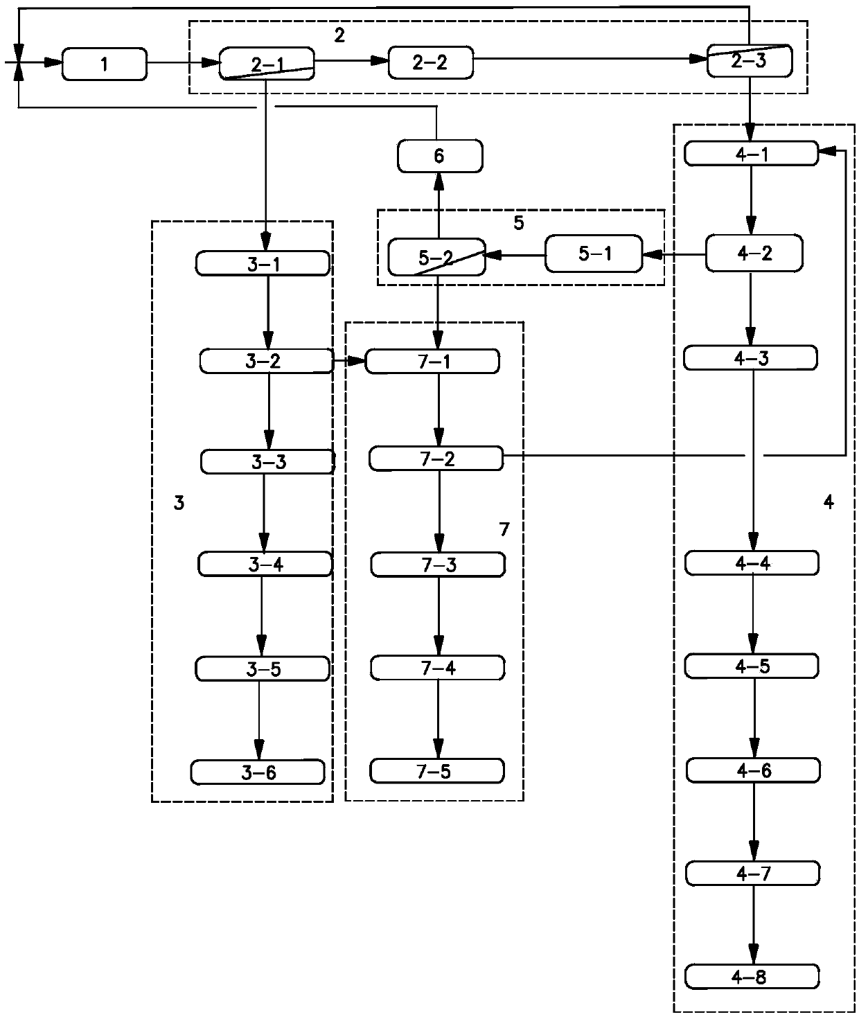
[0035] Such as figure 1 The high-salt wastewater salt separation system shown includes raw water tank 1, nanofiltration unit 2, sodium chloride evaporation crystallization unit 3, sodium sulfate evaporation crystallization unit 4, organic concentration unit 5, ozone reaction tank 6, mixed salt evaporation crystallization unit 7;

[0036] The water outlet of the raw water tank 1 communicates with the water inlet of the primary nanofiltration membrane device 2-1 of the nanofiltration unit 2, and a core filter is arranged on the pipeline connecting the raw water tank 1 and the primary nanofiltration membrane device 2-1 , the water outlet of the primary nanofiltration membrane device 2-1 communicates with the water inlet of the sodium chloride evaporation raw water pool 3-1 of the sodium chloride evaporation crystallization unit 3;

[0037] The outlet of the produced water of the secondary nanofiltration membrane device 2-3 of the nanofiltration unit 2 is connected with the water...

Embodiment 2

[0050] The high-salt wastewater salt separation system described in Example 1 is used to treat high-salt wastewater, including the following steps: process one nanofiltration; process sodium dichloride crystallization and sodium sulfate crystallization; process three organic concentration; process four ozone oxidation; process five Miscellaneous salt crystals; of which:

[0051] Process 1 nanofiltration: the pH in the raw water tank 1 is 7, the TDS concentration is 45000mg / L, and the Cl - Concentration 10000mg / L, SO 4 2- Concentration is 15000mg / L, COD is 1000ppm, total hardness is 1ppm high brine is sent in the first-level nanofiltration membrane device 2-1 of high-salt wastewater salinization system, and the first-level nanofiltration treatment is carried out under the pressure of 3MPa to obtain The primary nanofiltration product water and the primary nanofiltration concentrated water, and the primary nanofiltration product water mainly contains sodium chloride, and the pr...

Embodiment 3

[0058] The high-salt wastewater salt separation system described in Example 1 is used to treat high-salt wastewater, including the following steps: process one nanofiltration; process sodium dichloride crystallization and sodium sulfate crystallization; process three organic concentration; process four ozone oxidation; process five Miscellaneous salt crystals; of which:

[0059] Process 1 nanofiltration: the pH in the raw water tank 1 is 7, the TDS concentration is 50000 mg / L, and the Cl - Concentration 13000mg / L, SO 4 2- Concentration of 17000mg / L, COD of 800ppm, total hardness of 2ppm high salt water is sent to the first-stage nanofiltration membrane device 2-1 of the high-salt wastewater salt separation system, and the first-stage nanofiltration treatment is carried out under the pressure of 3MPa to obtain a First-level nanofiltration product water and first-level nanofiltration concentrated water, and the primary nanofiltration product water mainly contains sodium chlori...


PUM


Abstract

The invention discloses a high-salt wastewater salt separation system. The high-salt wastewater salt separation system comprises a raw water tank, a nanofiltration unit, a sodium chloride evaporationand crystallization unit, a sodium sulfate evaporation and crystallization unit, an organic concentration unit, an ozone reaction tank and a mixed salt evaporation and crystallization unit; and zero discharge of high-salt water can be achieved, water resources are saved, the environment is protected, operation is stable, safety and reliability are achieved, operating cost is low, and certain economic and social benefits are achieved. The invention further discloses a high-salt wastewater salt separation process. The high-salt wastewater salt separation process comprises the following steps ofstep one, nanofiltration, step two, sodium chloride crystallization and sodium sulfate crystallization, step three, organic concentration; step four, ozone oxidation, and step five, abraum salt crystallization. The water quality of produced reuse water meets the standard of ''Quality standards of reclaimed water for circulating cooling water HG-T3923-2007''; industrial sodium chloride produced reaches the A-level standard of refined industrial dry salt, and can be packaged for sale; and industrial sodium sulfate produced reaches first-class standard of I-class salt, and can be packaged for sale.

Description

Technical field: [0001] The invention relates to the field of wastewater treatment, in particular to a high-salt wastewater salt separation system and a process thereof. Background technique: [0002] Coal chemical enterprises will produce a large amount of high-salt wastewater during production and operation. High-salt wastewater has the characteristics of complex components, large fluctuations in water quality and quantity, high salt content, and high toxicity. At present, most of my country's coal chemical enterprises are concentrated in the western region with a fragile ecological environment. There is no sewage receiving water in the surrounding areas, and there is no condition for the discharge of waste water, so it must be treated before it can be discharged to the outside. At present, there are two commonly used methods for treating high-salt wastewater: 1. Use evaporation ponds to evaporate water. The problem is that the natural evaporation effect is not ideal, and i...

Claims


Application Information

Patent Timeline
Patent Type & Authority Applications(China)
IPC IPC(8): C01D3/06C02F1/00C01D5/00
CPCC01D3/06C02F1/00C01D5/00
Inventor 刘艳梅潘文刚乔宇王鑫陈强郝永刚魏渊刘尚利姚成盛王慧
Owner 内蒙古晶泰环境科技有限责任公司
Learn More