


Quick Research
Generate reliable direction feasibility study reports for your R&D in just a few steps.

Technical Q&A
Discover and master advanced knowledge NOW. Basics, ideas, possibilities, all at once.

Find Solutions
As an expert in R&D theories, this can generate solutions to your technical problems instantly.

Evaluate Feasibility
Analyze your overall solution with one click, know your potential R&D risks in advance.

Monitor Landscape
Get weekly tech updates, stay abreast of the latest tech innovations and key insights.
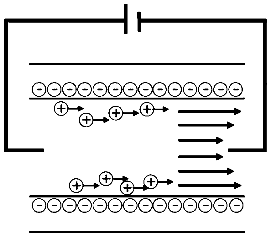
Low-voltage high-performance electroosmotic micropump chip based on solid-state track etching nanopores
A nanoporous and electroosmotic pump technology, applied in laboratory containers, laboratory utensils, fluid controllers, etc., can solve the problems of difficult microfluidic chip integration, high working voltage, and complicated operation, and achieve stable flow rate without any problems. Attenuation, low operating voltage, simple operation effect
- Summary
- Abstract
- Description
- Claims
- Application Information
AI Technical Summary
Problems solved by technology
Method used
Image

Examples
preparation example Construction
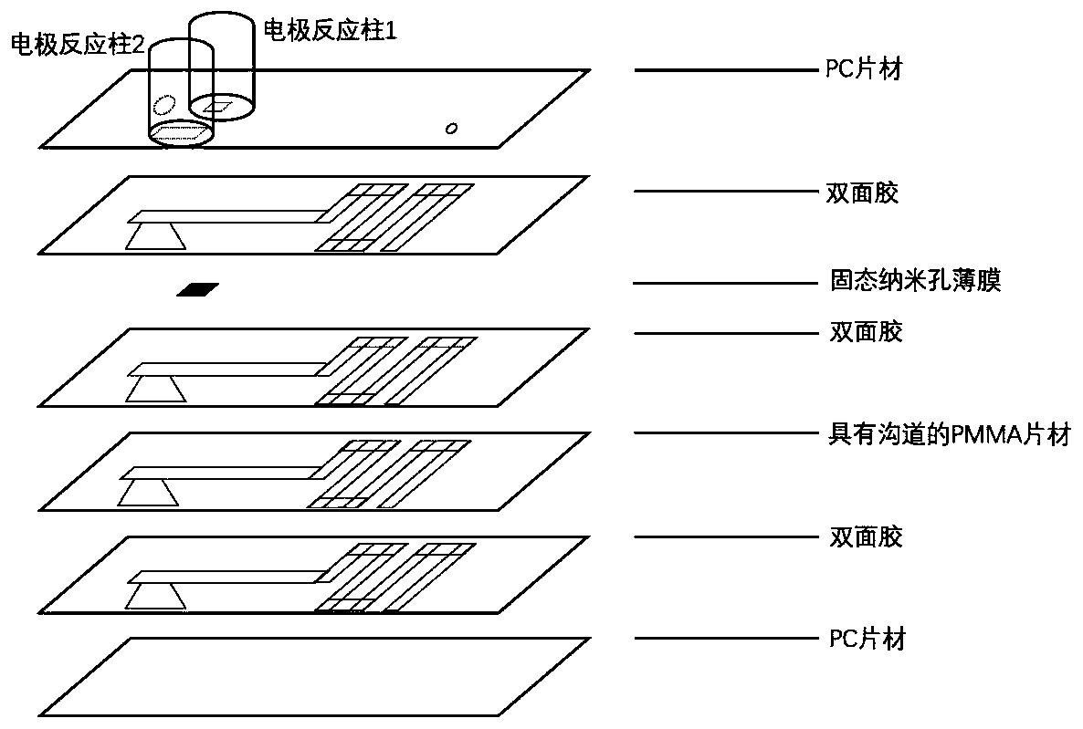
[0031] Step 1. Preparation of solid-state nanopores: the preparation of solid-state nanopores adopts the track etching method, which is a preparation method based on high-energy heavy ion irradiation and chemical etching. First, high-energy heavy ions are used to irradiate the polymer film material to form a nano-scale sneak track composed of damaged areas in the polymer film material; then chemical etching is used to selectively etch the sneak track, thereby A nano-sized pore structure is obtained. The diameter, shape and density of track-etched nanopores can be highly controllable by adjusting the irradiation conditions and etching conditions.
[0032] The ion track polymer film used above is the ion track polymer film after the bombardment of 17MeV / u Ar ions from the UNILAC accelerator of the Lanzhou Institute of Modern Physics, Chinese Academy of Sciences. ), cut the polymer film into a number of discs with a diameter of 2 cm, and irradiate them in a CL-1000 ultraviolet c...
Embodiment 1
[0038] Example 1 When the operating voltage is 50V, the current test of the electroosmotic pump chip under different reaction solutions
[0039] The specific experimental process is as follows:
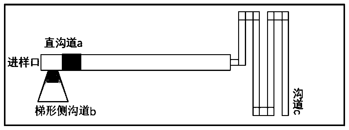
[0040] (1) Use a Pasteur pipette to take about 2ml of 0.1*TAE and add it to the electrode reaction column 1, 2 and the straight channel (a) of the chip, and seal the injection port with a sealing anti-collision sticker. During this operation, try to avoid air bubbles ; Insert platinum electrodes in the electrode reaction columns 1 and 2, connect the power supply and ammeter, set the voltage to 50V, and start timing after the circuit is connected. Currents were recorded every two minutes for one hour. During the experiment, pay attention to whether there is any leakage of the electroosmotic pump chip.
[0041] (2) After the recording is completed, turn off the voltage, take out the electrodes, empty the solution in the chip, and clean the electroosmotic pump chip with TAE at the next...
Embodiment 2
[0044] Example 2 Flow rate test of the electroosmotic pump chip under different reaction solutions and different voltages
[0045] The specific experimental process is as follows:
[0046] (1) Use a Pasteur pipette to take about 2ml of 0.1*TAE and add it to the electrode reaction column 1, 2 and the front section of the straight channel (a), and use a sealing anti-collision sticker to seal the injection port. During this operation, try to avoid air bubbles; Use a pipette gun to draw about 300 μL of diluted red ink and add it to the rear section of the straight channel (a), and seal the injection port with a sealing anti-collision sticker. During this operation, try to avoid generating air bubbles; in the electrode reaction column 1 and 2 Insert the platinum electrode, connect the power supply and the ammeter, set the voltage to 20V, and start timing after the circuit is connected. Record the advancing distance of the red ink in the channel (c) every two minutes; set the volta...
PUM
| Property | Measurement | Unit |
|---|---|---|
| Thickness | aaaaa | aaaaa |
| Outer diameter | aaaaa | aaaaa |
| The inside diameter of | aaaaa | aaaaa |
Abstract
Description
Claims
Application Information
 - R&D Engineer
- R&D Manager
- IP Professional
- Industry Leading Data Capabilities
- Powerful AI technology
- Patent DNA Extraction
Browse by: Latest US Patents, China's latest patents, Technical Efficacy Thesaurus, Application Domain, Technology Topic, Popular Technical Reports.
© 2024 PatSnap. All rights reserved.Legal|Privacy policy|Modern Slavery Act Transparency Statement|Sitemap|About US| Contact US: help@patsnap.com