A phosphorescent host compound and an electroluminescent device using the compound

A technology of electroluminescent devices and phosphorescent main bodies, which is applied in the manufacture of electric solid-state devices, semiconductor devices, semiconductor/solid-state devices, etc., can solve the problems of restricting the development of premix main body materials and short lifespan, so as to achieve crystallization and decomposition, improve efficiency and The effect of sufficient life and energy transmission

Active Publication Date: 2022-02-15
ZHEJIANG HUADISPLAY OPTOELECTRONICS CO LTD
View PDF9 Cites 0 Cited by
  • Summary
  • Abstract
  • Description
  • Claims
  • Application Information

AI Technical Summary

Problems solved by technology

[0003] At present, the blue phosphorescent system has stopped at the laboratory stage due to its short lifespan. The green and red phosphorescent doped systems have been successfully applied in commercial fields, such as mobile phones, lighting and large-size TVs, so how to improve the green and red light The luminous efficiency of the phosphorescent luminescent system has attracted the attention of the industry, and the most successful is the development and utilization of Premix theme materials. Mixing creates hole and electron traps in the light-emitting layer, thereby improving the luminous efficiency of the material, but it is required that the P-type host and the N-type host have the same evaporation temperature, and the P-type host material and the N-type host material are evaporated for a long time The proportions will not change, which severely limits the development of premix body materials

Method used


Image

  • A phosphorescent host compound and an electroluminescent device using the compound
  • A phosphorescent host compound and an electroluminescent device using the compound
  • A phosphorescent host compound and an electroluminescent device using the compound

Examples


Embodiment 1

[0059] Example 1: Synthesis of Compound 4

[0060] 1, synthesis of intermediate SUB-1

[0061]

[0062] Under nitrogen protection, 3-amino-2-indol methitrile (23.27 g, 149 mmol), tetrahydrofuran (200 mL) was added, and phenyl bromide (87 mL, 3.0 mol / L, solvent) was added dropwise. ET 2 O) and stirred at 0 ° C for 1 hour. Ethyl chloroformate (19.4 g, 179 mmol) was added dropwise, and about 1 hour. The solution was adjusted with ammonium chloride until it became a microalic acid, and washed with water and heptane to give an intermediate [SUB-1] 34.37 g (yield 80%). The resulting compound is determined by LC-MS. Mass spectrometry M / Z, theoretical value: 288.34; measured value: 288.13. Theoretical element content (%) C 19 Hide 16 N 2 O: C, 79.14; H, 5.59; N, 9.72; O, 5.55.

[0063] 2, the synthesis of intermediate SUB-2

[0064]

[0065] Under nitrogen protection, [SUB-1] (31.71 g, 110 mmol) was added to about 80 ml of thiol chloride, and after refluxing overnight, cooled to -...

Embodiment 2

[0069] Example 2: Synthesis of Compound 5

[0070] The compound 5 was obtained from the synthesis method in Example 1. The resulting compound is determined by LC-MS. Mass spectrometry M / Z, theoretical value: 678.82; measured value: 678.29. Theoretical element content (%) C 49 Hide 34 N 4 : C, 86.70; H, 5.05; N, 8.25.


PUM


Abstract

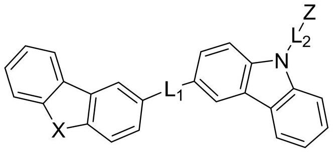
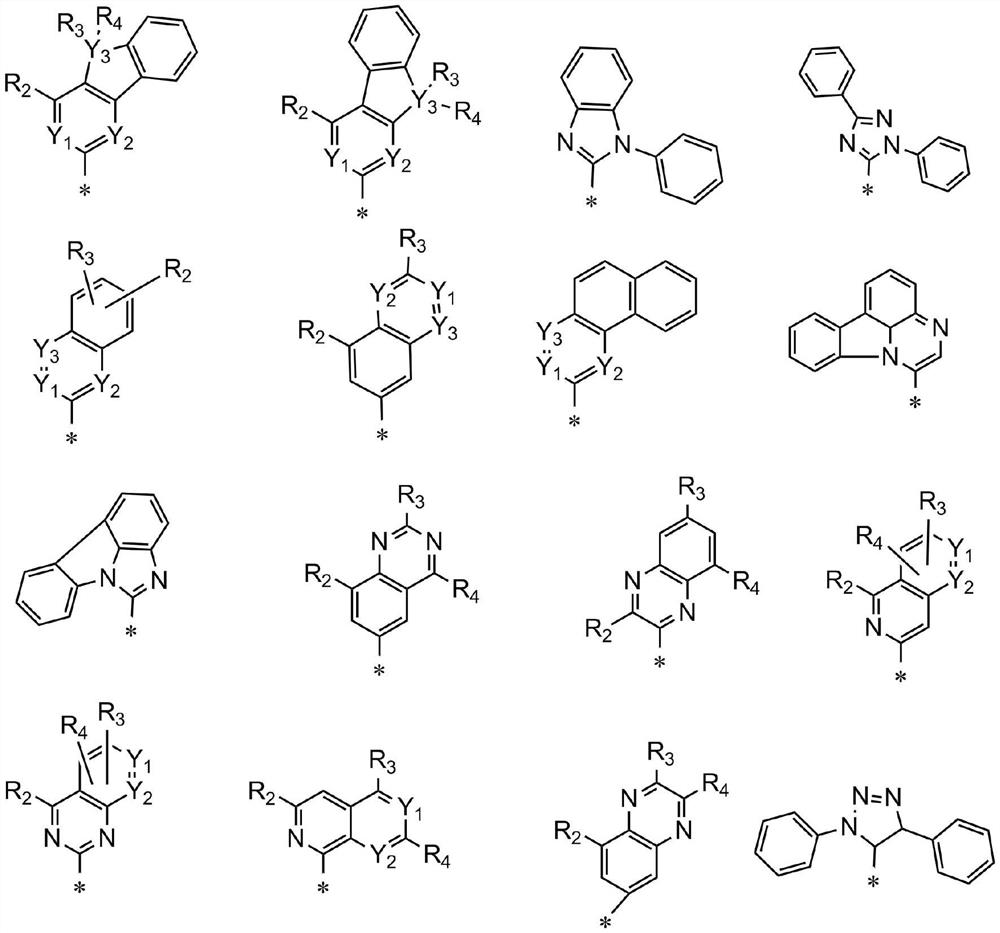
The invention discloses a novel phosphorescent host compound and an electroluminescent device using the compound. The organic compound is shown in structural formula I: in structural formula I, L 1 , L 2 Independently selected from single bond, phenylene, naphthylene, Z independently selected from H, C6-C30 aryl, C2-C30 heteroaryl; X independently selected from O, S, Se, NR 1 , C(R 1 ) 2 , Si(R 1 ) 2 , where R 1 independently selected from hydrogen, substituted or unsubstituted C1-C20 alkyl, substituted or unsubstituted C1-C20 alkoxy, C6-C30 aryl or C2-C30 heteroaryl. The phosphorescent host compound of the present invention has better thermal stability, and the deeper HOMO and shallower LUMO can surround the HOMO and LUMO of the dopant, which can balance the transfer of holes and electrons, and the energy transfer is more sufficient. Can effectively improve the efficiency and life of the device.

Description

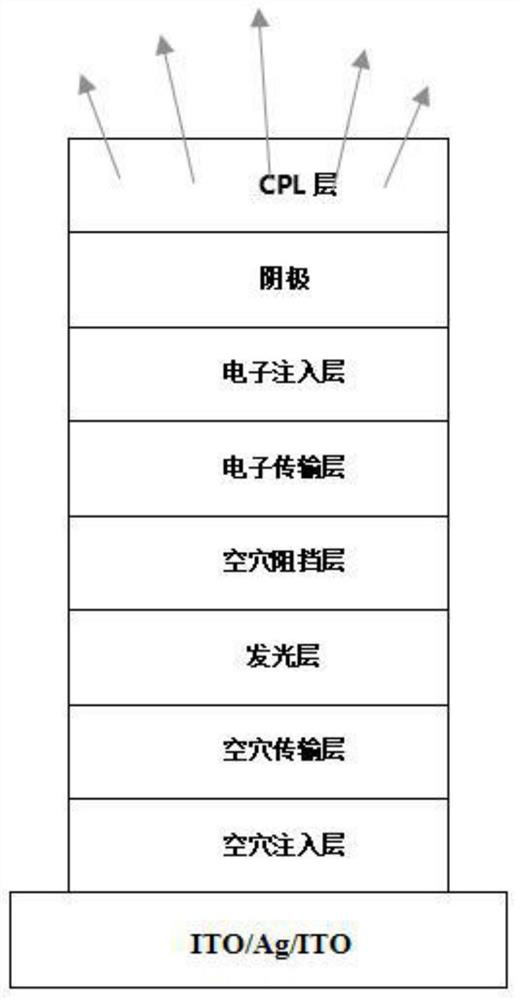
Technical field [0001] The present invention relates to an organic electroluminescent field, in particular a novel phosphorescent body compound and an electroluminescent device using the compound. Background technique [0002] The luminescence of the OLED belongs to the Eletro Luminescence EL. Due to the importance of the application, electricity luminescence phenomena has always been an interested science. Organic glowing phenomenon is the first 1963 by Professor Pope, At that time, he applied hundreds of volts in the anthracene crystal, observed the glowing phenomenon, which is the earliest literature. This phenomenon has not received much attention due to excessive voltages and poor luminous efficiency. By 1987, Dr. Koda, Kodak, and Steve, and Steve released a multilayer OLED device in vacuum vapor deposition, but holes and electronically transmissions The interface attachment of the layer is combined, which greatly improves the performance of the device, its working voltage a...

Claims


Application Information

Patent Timeline
Patent Type & Authority Patents(China)
IPC IPC(8): C07D487/06C07D403/14C07D471/04C09K11/06H01L51/50H01L51/54
CPCC07D487/06C07D403/14C07D471/04C09K11/06C09K2211/1007C09K2211/1029C09K2211/1044C09K2211/1059C09K2211/1088C09K2211/1011H10K85/615H10K85/6574H10K85/6572H10K50/11
Inventor 汪华月华万鸣申屠晓波
Owner ZHEJIANG HUADISPLAY OPTOELECTRONICS CO LTD
Why Eureka
Try Eureka