Ultra-wideband band-pass filter with transmission zero point

A band-pass filter and transmission zero technology, applied in waveguide devices, electrical components, circuits, etc., can solve problems such as difficulty in introducing transmission zeros, unfavorable miniaturization design, and difficult structural forms, so as to reduce size cost and structure The effect of compact, good notch characteristics

Inactive Publication Date: 2019-12-20
10TH RES INST OF CETC
View PDF4 Cites 11 Cited by
  • Summary
  • Abstract
  • Description
  • Claims
  • Application Information

AI Technical Summary

Problems solved by technology

However, this solution will bring an additional increase in the size of the entire filter, which is not conducive to the realization of miniaturized design
The design of UWB filter mainly has the following difficulties: (1) The relative bandwidth has reached 110%, and the commonly used narrowband and broadband filter design methods (such as [3] parallel coupling type, interdigitated type) are no longer applicable, and need New theories and design methods have been proposed and applied; (2) There are higher requirements on performance (such as in-band insertion loss and group delay are smaller)
(3) The frequency band span is too large, and there are many other narrow-band transmission signals in the band (such as: WiMAX: 3.3GHz-3.6GHz, satellite C-band: 3.7GHz-4.2GHz, WLAN:

Method used


Image

  • Ultra-wideband band-pass filter with transmission zero point
  • Ultra-wideband band-pass filter with transmission zero point
  • Ultra-wideband band-pass filter with transmission zero point

Examples


Embodiment Construction

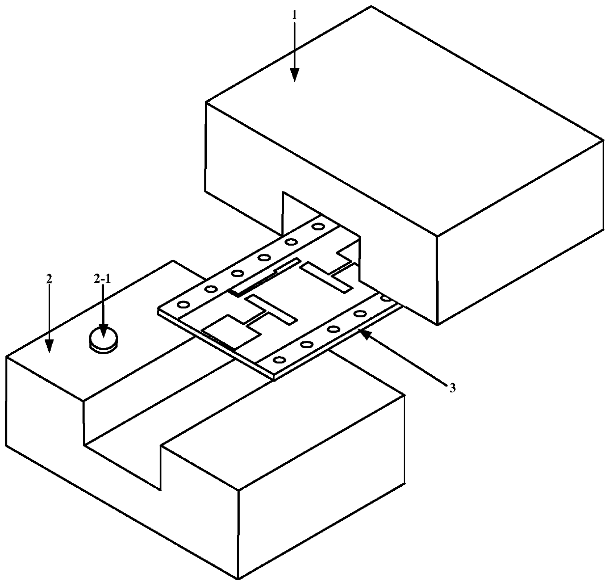
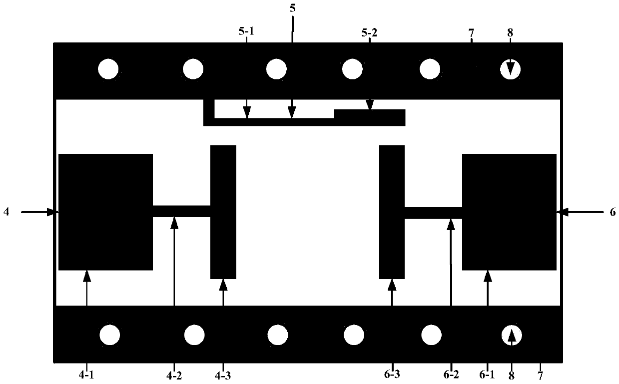
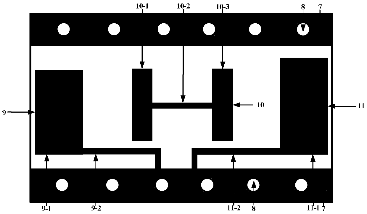
[0021] refer to Figure 1-Figure 3 . In the preferred embodiment described below, a kind of ultra-wideband band-pass filter with transmission zero, comprises: the metal upper cavity 1 that is shaped on the lower opening groove, the metal lower cavity 2 that is shaped on the upper opening groove and fixing The dielectric substrate 3 between the above-mentioned upper and lower metal lower chambers, and the metal ground pass bands 7 arranged longitudinally and symmetrically on the front, back, and lower sides of the dielectric substrate 3, on the wide sides of the front and back sides of the dielectric substrate 3, Symmetrically etched a dumbbell rectangular head defect pattern with two symmetrical air bridges constrained between the metal ground passband 7, wherein: the dumbbell rectangular head is divided into the first dumbbell rectangular head, the second dumbbell head, the third dumbbell 9 and the first dumbbell Four dumbbell heads 11, the first rectangular dumbbell head an...


PUM


Abstract

The invention discloses an ultra-wideband band-pass filter with a transmission zero point, and aims to provide a band-pass filter with the excellent trapped wave characteristic and standing wave performance. The ultra-wideband band-pass filter with the transmission zero point is realized by the following technical scheme that dumbbell rectangle heads of two symmetric air bridges restricted betweenmetal ground passbands are symmetrically etched on the wide edges of the left and right sides of each of the front and back surfaces of a dielectric substrate, the first dumbbell head located at theproximal end of the wide edge of the dielectric substrate forms an equivalent circuit of a first resonator and lumped parameters of the first resonator in a manner that a first high-impedance short-circuit branch is vertically connected with a first low-impedance open-circuit branch of a terminal, and the second dumbbell head located at the far end of the wide edge of the dielectric substrate forms an equivalent circuit of a second resonator with a dual relationship with the first resonator and lumped parameters of the second resonator; and an equivalent circuit of a third resonator and lumpedparameters of the third resonator, composed of an H-shaped branch, falls in a cup-shaped cross section formed by synthesizing two flag shapes oppositely and symmetrically, wherein the first resonatorsequentially transmits signals to the second resonator and the third resonator to form a main transmission link path.

Description

technical field [0001] The invention is suitable for radio frequency microwave communication systems, and can be widely used in ultra-wideband band-pass filters at the front end of ultra-wideband communication systems. Background technique [0002] Filters are one of the indispensable devices in wireless communication systems. In the communication system, the signal will be interfered by the environmental noise signal outside the system, as well as the harmonic influence in the system due to the nonlinearity of the system, which will significantly reduce the communication quality of the communication system. In order to suppress the interference signal outside the system and the harmonic signal generated by nonlinearity in the system, it is necessary to add a filter to the system to ensure that the useful signal can pass through with a small loss, and the useless signal can be suppressed greatly. [0003] With the rapid development of mobile communication technology, ultra-...

Claims


Application Information

Patent Timeline
IPC IPC(8): H01P1/212
CPCH01P1/212
Inventor 徐照旭钟鸣海蔡喆
Owner 10TH RES INST OF CETC
Why Eureka
Try Eureka