Gas purification reactor and gas purification method

A gas purification and reactor technology, applied in chemical instruments and methods, inert gas compounds, specific gas purification/separation, etc., can solve problems such as high cost and complex structure, achieve simple structure, improve purification effect, and reduce energy consumption Effect

Pending Publication Date: 2020-02-07
LONGI GREEN ENERGY TECH CO LTD +1
View PDF8 Cites 0 Cited by
  • Summary
  • Abstract
  • Description
  • Claims
  • Application Information

AI Technical Summary

Problems solved by technology

In the process of purifying and removing impurities of inert gas, the existing reactors mostly adopt a tower structure, which has the problems of complex structure and high cost

Method used


Image

  • Gas purification reactor and gas purification method

Examples


Embodiment 1

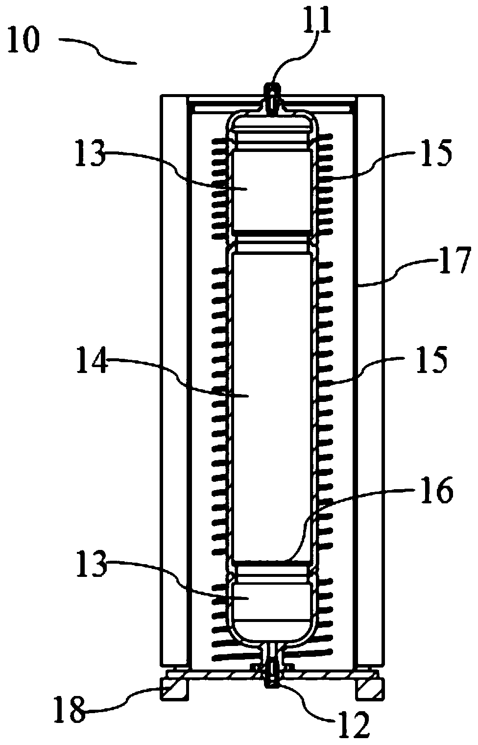
[0026] In the gas purification reactor 10 provided by the present invention, an air inlet 11 and an air outlet 12 are respectively arranged at both ends, the air inlet 11 is connected with the furnace body pipeline, receives used inert gas for crystal growth containing impurities, and the air outlet 12 Connect with other reactors or gas pipelines. The gas purification reactor 10 is filled with gas purification materials. In this embodiment, the gas purification materials can be iron-based, copper-based, nickel-based or composite oxygen carrier materials, preferably with a small amount of catalyst. The gas purification material catalyzes the oxidation of carbon-containing gas and / or hydrogen-containing gas in the inert gas, and absorbs impurities in the gas.

[0027] The gas purification reactor 10 includes at least one gas buffer chamber 13 and at least one gas purification chamber 14 . One end or two ends of the gas purification chamber 14 are connected to a gas buffer chamb...

Embodiment 2

[0035] This embodiment provides a gas purification method using the gas purification reactor 10 as described above, comprising the following steps:

[0036] filling the gas purification chamber 14 of the gas purification reactor 10 with gas purification material;

[0037] Heating the gas purification chamber to the corresponding temperature T 1 , Heating the gas buffer chamber to the corresponding temperature T 2 ;

[0038] The gas enters from the gas inlet 11 of the gas purification reactor 10 and is discharged from the gas outlet 12 .

[0039] Of course, a plurality of gas purification reactors 10 can also be connected to each other, for example, a plurality of gas purification reactors 10 are connected in series through an inlet 11 and a gas outlet 12, or a plurality of gas purification reactors 10 are connected in series through an inlet 11. The gas outlet 12 and the gas pipeline are connected in parallel with each other.

[0040] The gas inlet 11 and the gas outlet 12 o...


PUM


Abstract

The invention discloses a gas purification reactor. The gas purification reactor is used for absorbing impurities in gas, and comprises at least one gas purification chamber, wherein the gas purification chamber is of a tubular structure, and is filled with a gas purifying material, and the temperature T1 of the gas purification chamber is not smaller than 300 DEG C and not larger than 600 DEG C.A gas purification method comprises the steps: filling the gas purification chamber of the gas purification reactor with the gas purifying material, heating the gas purification chamber to a corresponding temperature T1, heating a gas buffer chamber to a corresponding temperature T2, introducing gas into a gas inlet of the gas purification reactor, and performing discharge from a gas outlet. Through arrangement of a reasonable temperature range for the gas purification chamber, the activity of the gas purifying material can be adjusted, and the purification effect is improved; through arrangement of the gas buffer chamber, the gas flow rate is buffered, and the gas is preheated; through arrangement of a partition plate between the gas buffer chamber and the gas purification chamber, gas flow is dispersed, the gas flow rate is reduced, the gas flow is prevented from driving the gas purifying material to flow, and the purifying material is prevented from getting out of the partition plate under the impact action of the gas flow.

Description

technical field [0001] The invention belongs to the technical field of single crystal silicon material preparation, and in particular relates to a gas purification reactor and a gas purification method. Background technique [0002] In the process of crystal growth such as monocrystalline silicon and polycrystalline silicon, it is necessary to introduce inert gas into the furnace to stabilize the furnace pressure and take away impurities such as volatiles and oxides to improve the stability of crystal growth and product quality. The existing inert gas used for crystal growth, such as argon, is mostly used for one-time use; it is discharged after passing through the furnace once, resulting in waste of inert gas resources. From Czochralski single crystal furnaces, polycrystalline ingot furnaces and other equipment, the purity of the used inert gas is reduced due to impurities such as carbon monoxide and hydrocarbons. In order to improve the purity of the recovered gas, a reac...

Claims


Application Information

Patent Timeline
Patent Type & Authority Applications(China)
IPC IPC(8): C01B23/00
CPCC01B23/0094C01B2210/0004C01B2210/0015
Inventor 付泽华周锐张军社邓浩李侨张镇磊徐战军朱永刚刘永生谢志宴
Owner LONGI GREEN ENERGY TECH CO LTD
Why Eureka
Try Eureka