Edge sensor for segmented mirror surface based on interference principle and working method thereof

A sensor and edge technology, which is applied in the field of edge sensors for splicing mirrors, can solve the problems of limited inspection batches, high prices, and impact on measurement accuracy, and achieve the effects of convenient installation, debugging, low installation accuracy requirements, and simple process principles

Active Publication Date: 2020-02-11
NANJING INST OF ASTRONOMICAL OPTICS & TECH NAT ASTRONOMICAL OBSE
View PDF10 Cites 3 Cited by
  • Summary
  • Abstract
  • Description
  • Claims
  • Application Information

AI Technical Summary

Problems solved by technology

[0003] The above-mentioned multiple methods and the displacement sensors realized by them all have various disadvantages.
Contact measurement installs displacement sensors on the back or side of the mirror, and often needs to use other instruments to calibrate the sensor at the high and low positions, such as Keck, SALT, LAMOST telescope splicing primary mirrors, etc., which cannot directly reflect the absolute error state of mirror splicing; and optical fiber Although the displacement sensor can directly reflect the height of the mirror surface, because it uses optical energy detection, it will bring the impact of various factors such as stray light to the optical system (of course, it can be avoided by sealing measures), and the distance between the end face of the optical fiber and the mirror surface will affect the measurement Accuracy: The pupil plane detection and image plane detection methods based on the optical detection system will be affected by changes in various environmental factors such as atmospheric turbulence, temperature changes, noise, etc., with limited precision and limited batches of detection, and limited use occasions
[0004] A high-precision capacitive displacement sensor (CN201010120779.2) that directly detects the height difference of the mirror surface without contact. Although it can directly measure the height difference of the mirror surface and has high precision, the capacitive sensor is greatly affected by the environment, is expensive, and can only measure the height difference of the mirror surface. , it is impossible to obtain multiple degrees of freedom errors of mirror stitching error (dihedral angle error and mirror height difference) at the same time

Method used


Image

  • Edge sensor for segmented mirror surface based on interference principle and working method thereof
  • Edge sensor for segmented mirror surface based on interference principle and working method thereof
  • Edge sensor for segmented mirror surface based on interference principle and working method thereof

Examples


Embodiment 1

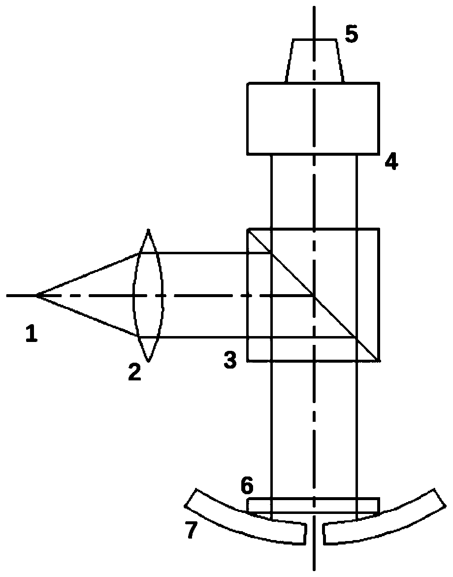
[0036] Embodiment 1, with reference to figure 1 : place a flat crystal 6 on the seam of the concave spherical splicing mirror 7 in the figure or on both ends (corner points) of the seam (there may be a simple thin pad to avoid contact damage and not affect the measurement and processing), light source 1 and collimation The mirror 2 forms a collimated parallel beam, and the parallel beam enters the optical path through the semi-transparent and half-reflective prism 3 outside the optical path and then vertically incident on the flat crystal 6 and the splicing mirror 7, the front surface of the flat crystal 6 is coated with an anti-reflection film, and the rear surface is coated with a part of the reflective part Transmissive film (making the energy of the two reflected light beams from the flat crystal 6 back to the half-reflective prism 3 close to each other, forming equal-thickness interference fringes), the interference fringes pass through the microscope 4, imaged on the dete...

Embodiment 2

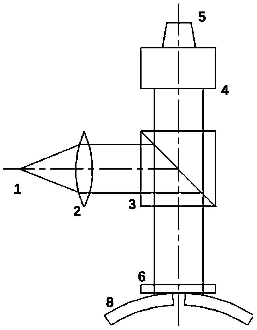
[0037] Embodiment 2, with reference to figure 2 , is basically the same as Embodiment 1, but the splicing mirror surface 8 is a convex spherical or aspheric mirror; the fringes are imaged on the detector 5, and are also image-processed by a computer to obtain the splicing mirror error. The light intensity distribution of the equal-thickness interference fringes in this example is slightly different from that in Example 1, but the processing method is the same, by fitting the light intensity distribution or by changing the image center and radius.

Embodiment 3

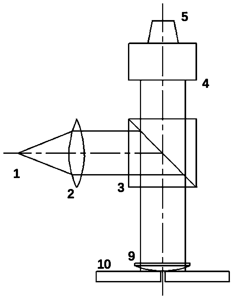
[0038] Embodiment 3, with reference to image 3 , is basically the same as Embodiment 1 and Embodiment 2, but the splicing mirror surface 10 is a plane mirror, and what is matched to realize equal-thickness interference fringes is a plano-convex lens 9; the parallel light beam enters the optical path through the semi-transparent and half-reflective prism 3 outside the optical path and then enters the optical path vertically To the plano-convex lens 9 and the splicing mirror surface 10, the front surface of the plano-convex lens 9 is plated with an anti-reflection film, and the rear surface is plated with a partly reflective and partially transmissive film (making the energy of the two beams of reflected light beams that are returned to the half-transparent prism 3 from the plano-convex lens 9 be close at last, Form equal-thickness interference fringes), the fringes are imaged on the detector 5, and are also image-processed by the computer to obtain the splicing mirror error. T...


PUM


Abstract

The invention discloses an edge sensor for a segmented mirror surface based on an interference principle, and a working method thereof. The edge sensor is characterized in that: an optical flat or spherical lens is placed on a sub-mirror splicing seam of a measured segmented mirror surface, the front surface of the optical flat or spherical lens is completely anti-reflection, and the rear surfaceof the optical flat or spherical lens is provided with a coating film; a parallel light source is arranged on the other side of a sub-mirror of the measured segmented mirror surface and the optical flat or spherical lens, light rays vertically enter the optical flat or spherical lens by means of a semi-reflecting and semi-transmitting prism and then part of the light beam on the surface returns, the other part is reflected by the surface of the sub-mirror along an original path, the two beams of reflected light form interference fringes, the interference fringes enter a microscopic amplification imaging system by means of the semi-reflecting and semi-transmitting prism, and target surface receiving and digital imaging are carried out by means of a CCD or CMOS detector, namely, the splicingerror of the adjacent sub-mirrors can be handled. The edge sensor prevents starlight and wavefront sensors from occupying and wasting a limited high-imaging-quality field of view of an optical system, is low in price, stable in performance and not affected by environmental factors, and is suitable for detecting the splicing errors between the adjacent sub-mirrors of various optical segmented mirror surfaces.

Description

technical field [0001] The invention relates to a contact edge sensor for splicing mirrors based on the principle of interference, which is used in various splicing mirror optical systems, especially for splicing astronomical telescope mirror splicing error detection (including confocal and common phase splicing mirror active optics) system). The invention also relates to the working method of the edge sensor for splicing mirrors based on the principle of interference. Background technique [0002] High-precision sensor technology is an inevitable choice for the high development of science and technology. There are many common sensors that can be used to detect the height of the mirror surface when splicing astronomical telescope mirrors, mainly divided into contact type and non-contact type, direct detection type and indirect detection type, etc.; contact type mainly includes capacitors installed on the back or side of the mirror surface , inductance, eddy current and oth...

Claims


Application Information

Patent Timeline
Patent Type & Authority Applications(China)
IPC IPC(8): G01B11/00G01B11/02G01B9/02
CPCG01B9/02G01B11/00G01B11/02
Inventor 张勇张茜倪季君李烨平
Owner NANJING INST OF ASTRONOMICAL OPTICS & TECH NAT ASTRONOMICAL OBSE
Why Eureka
Try Eureka