Control system and control method for asymmetric secondary side current of buck-boost resonant converter

A resonant converter, secondary current technology, applied in the control/regulation system, the irreversible DC power input is converted into AC power output, the AC power input is converted into DC power output, etc. It can solve the problems of long and increase loss, so as to achieve the effect of easy control method, average heat generation, and reduction of heat loss

Inactive Publication Date: 2020-02-11
SOUTHEAST UNIV
View PDF5 Cites 4 Cited by
  • Summary
  • Abstract
  • Description
  • Claims
  • Application Information

AI Technical Summary

Problems solved by technology

[0002] The rectification network on the secondary side of the buck-boost resonant converter outputs a DC voltage through the synchronous rectifier tube and the output capacitor, but due to the asymmetry of the primary side resonant current of the buck-boost resonant converter, the secondary side rectification network flows through two and a half cycles The current of the output capacitor is inconsistent, so that the voltage value of the output capacitor terminal varies widely, resulting in unacceptable ripple
Ripples can easily lead to harmonic voltages on electrical equipment. In many cases, harmonic voltages will distort sine waves, resulting in increased hysteresis and eddy current losses in electrical equipment such as transformers and capacitors, and increased copper losses in transformers. Therefore, transformers will generate Local overheating accelerates insulation aging and service life and reduces power supply reliability
Secondly, ripple will also increase additional loss and reduce power efficiency
Strong ripples will cause surge voltage or current, which will cause electrical appliances to burn out
[0003] In the prior art, the control strategy is mainly to solve the asymmetry of the secondary side current of the buck-boost resonant converter through asymmetric control, but when the difference of the current flowing in the secondary side rectification network within two half cycles is too large, , each adjustment of the conduction time of the power tube is a fixed value, and the conduction time of the power tube cannot be adjusted according to the difference in the current flowing through the secondary side rectification network. Therefore, when the difference is too large, the required adjustment The cycle is long and the adjustment speed is slow, which affects the efficiency of the converter

Method used


Image

  • Control system and control method for asymmetric secondary side current of buck-boost resonant converter
  • Control system and control method for asymmetric secondary side current of buck-boost resonant converter
  • Control system and control method for asymmetric secondary side current of buck-boost resonant converter

Examples


Embodiment 1

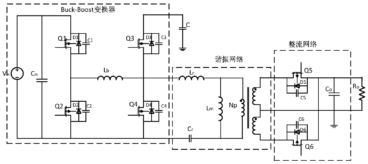
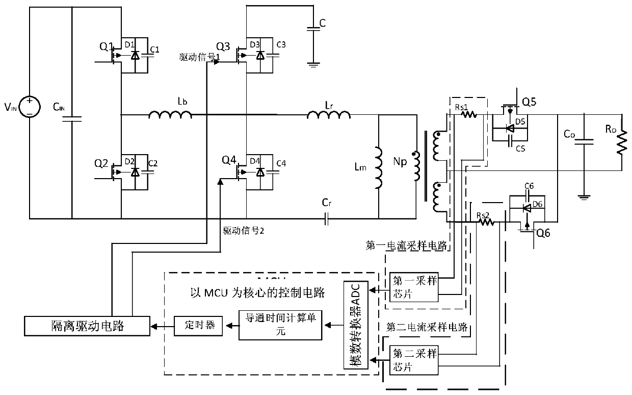
[0039] Example 1. The schematic circuit diagram of the control system for the secondary side current asymmetry of the buck-boost resonant converter proposed by the present invention is as follows: figure 2 shown.

[0040] The control system for the asymmetry of the secondary side current of the buck-boost resonant converter includes: a first current sampling circuit, a second current sampling circuit, a control circuit with an MCU as the core, and an isolation drive circuit.

[0041] The first current sampling circuit includes: a first sampling chip and a first sampling resistor Rs1. The first sampling resistor Rs1 is connected in series between the first secondary winding of the transformer Tr and the first synchronous rectifier tube Q5, the two ends of the first sampling resistor Rs1 are respectively connected to the two input terminals of the first sampling chip, and the The output terminal is connected to the control circuit with MCU as the core.

[0042] The second cu...

Embodiment 2

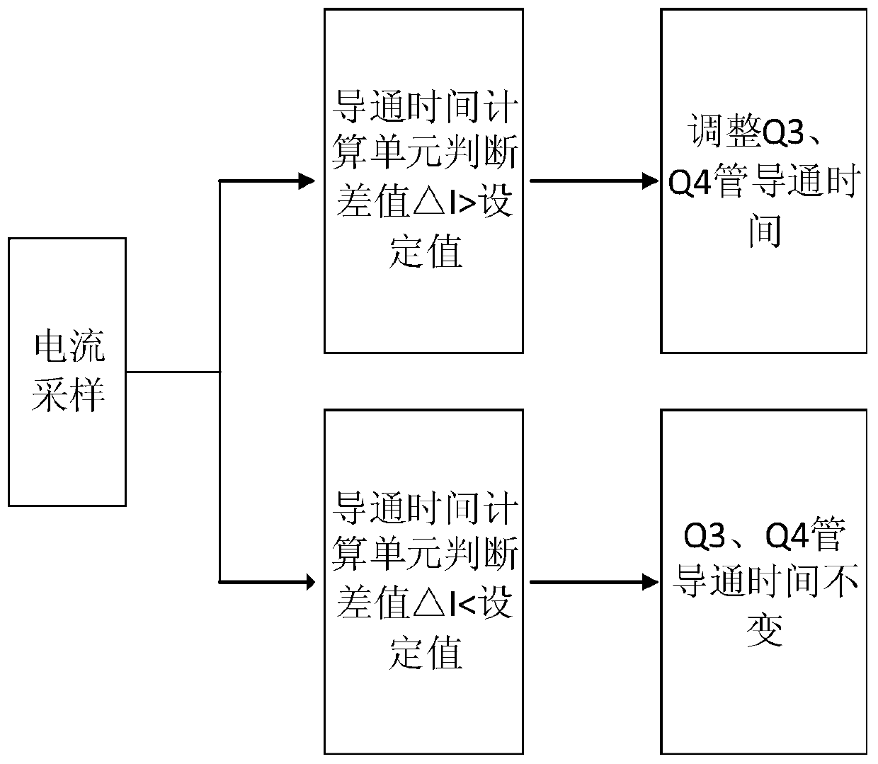
[0054] Example 2. The system block diagram of the control method for the secondary side current asymmetry of the buck-boost resonant converter proposed by the present invention is as follows image 3 shown. Wherein the third pre-stage power tube Q3 and the fourth pre-stage power tube Q4 are complementary conduction, therefore, reducing the conduction time of the third pre-stage power tube Q3 will correspondingly increase the conduction time of the fourth pre-stage power tube Q4, Increasing the conduction time of the third pre-stage power transistor Q3 correspondingly reduces the conduction time of the fourth pre-stage power transistor Q4.

[0055] When the buck-boost resonant converter is in a stable working state, when the resonant current on the primary winding side of the transformer is distorted, the current flowing in the rectification network on the secondary winding side will be asymmetrical in the first half cycle and the second half cycle . Therefore, the current p...

Embodiment 3

[0066] Example 3. Figure 4 In the case of primary side current distortion, when the control method proposed by the present invention is not used, the schematic diagrams of the transformer secondary rectifier tube current in the first half cycle and the second half cycle, the solid line in the figure represents the current of the first rectifier tube Q5, and the dotted line represents the current of the first rectifier tube Q5. The current of the second rectifier tube Q6. Figure 5 In the case of primary side current distortion, when using the control method proposed by the present invention, the transformer secondary rectifier tube current schematic diagram of the first half cycle and the second half cycle, the solid line in the figure represents the current of the first rectifier tube Q5, and the dotted line represents the second rectifier tube Q5. The current of the rectifier tube Q6.

[0067] Comparing the two figures, it is obvious that under the condition of primary cur...


PUM


Abstract

The invention provides a control system and a control method for asymmetric secondary side current of a buck-boost resonant converter, which belong to the technical field of resonant converter control. The control system comprises a first current sampling circuit, a second current sampling circuit, a control circuit taking an MCU as a core, and an isolation driving circuit. Under the condition ofprimary side current distortion, after sampling of a plurality of working periods, a difference value between current peak value average values of an upper half period and a lower half period of a secondary side rectification network of the converter is obtained, logic comparison is carried out on the difference value and a set value, and secondary side current of the converter is enabled to be symmetrical by adjusting conduction time of a preceding-stage power tube of a primary side of the converter. The control system is simple in structure and the control method is easy to implement. The secondary side current of the transformer is symmetrical, the heat loss is reduced, and the efficiency is improved.

Description

technical field [0001] The invention relates to the technical field of control of a buck-boost resonant converter, in particular to a control system and a control method for asymmetric secondary side currents of a buck-boost resonant converter. Background technique [0002] The rectification network on the secondary side of the buck-boost resonant converter outputs a DC voltage through the synchronous rectifier tube and the output capacitor, but due to the asymmetry of the primary side resonant current of the buck-boost resonant converter, the secondary side rectification network flows through two and a half cycles The inconsistent current makes the output capacitor terminal voltage vary widely, resulting in unacceptable ripple. Ripples can easily lead to harmonic voltages on electrical equipment. In many cases, harmonic voltages will distort sine waves, resulting in increased hysteresis and eddy current losses in electrical equipment such as transformers and capacitors, and...

Claims


Application Information

Patent Timeline
Patent Type & Authority Applications(China)
IPC IPC(8): H02M3/335H02M3/158H02M7/48
CPCH02M3/1584H02M3/33592H02M7/48H02M7/4815Y02B70/10
Inventor 钱钦松郑敏刘琦刘斯扬孙伟锋时龙兴
Owner SOUTHEAST UNIV
Why Eureka
Try Eureka