Piezoelectric composite film and preparation method thereof

A piezoelectric composite, composite thin film technology, applied in the manufacture/assembly of piezoelectric/electrostrictive devices, piezoelectric/electrostrictive devices, piezoelectric/electrostrictive/magnetostrictive devices, etc. Affect the bonding process, high risk, complex process and other problems, to achieve the effect of reducing reverse pattern distortion, improving accuracy, and solving high risk

Pending Publication Date: 2020-02-21
JINAN JINGZHENG ELECTRONICS
View PDF4 Cites 8 Cited by
  • Summary
  • Abstract
  • Description
  • Claims
  • Application Information

AI Technical Summary

Problems solved by technology

Therefore, the polarization inversion process in the prior art has defects such as high risk, complex process, poor controllability, and poor repeatability, and limits the fineness and complexity of the corresponding graphics, which makes it possible to design and manufacture relatively wide and relatively simple graphics
[0006] In addition, due to t

Method used


Image

  • Piezoelectric composite film and preparation method thereof
  • Piezoelectric composite film and preparation method thereof
  • Piezoelectric composite film and preparation method thereof

Examples


Embodiment 1

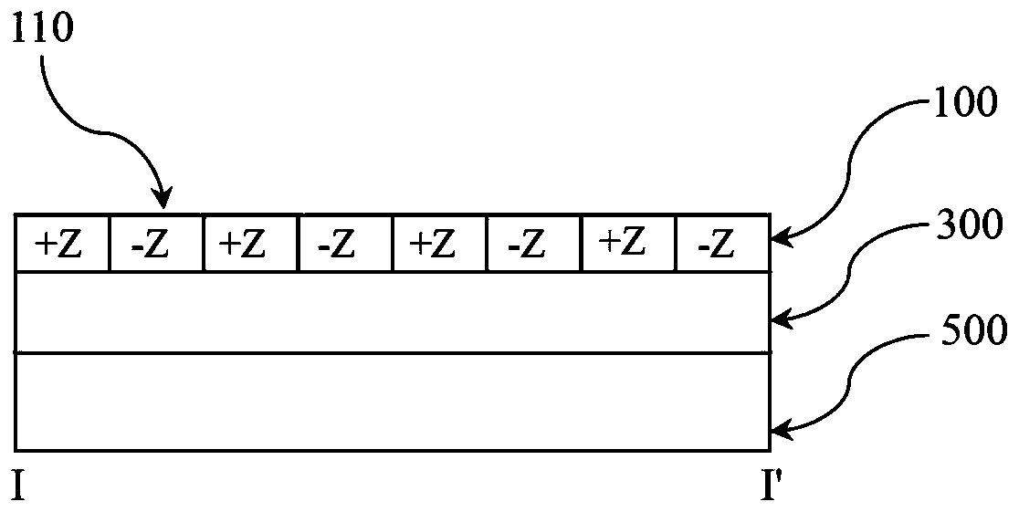
[0058] Firstly, a pre-piezoelectric composite film including a substrate, an isolation layer and a piezoelectric crystal film layer stacked in sequence is prepared. In the pre-piezoelectric composite film, the stacked structure of piezoelectric crystal film layer / isolation layer / substrate can be, for example, LT / SiO2 / Si with a thickness of 500nm / 3um / 400um respectively, wherein the polarization direction of the LT layer is + Z.

[0059] Next, a protective layer is formed on the piezoelectric crystal film layer by using a photoresist, and the protective layer is patterned through a photolithography process to obtain a pattern of the protective layer. The thickness of the protective layer is 3um-6um.

[0060] Next, an ion implantation process is performed on the region of the pre-piezoelectric composite thin film exposed by (or not covered by) the protective layer. Specifically, in this embodiment, the implanted ions may be He + , the implant energy can be about 150keV, and th...

Embodiment 2

[0064] Firstly, a pre-piezoelectric composite film including a substrate, an isolation layer and a piezoelectric crystal film layer stacked in sequence is prepared. In the pre-piezoelectric composite film, the stacked structure of piezoelectric crystal film layer / isolation layer / substrate can be, for example, LN / SiO2 / Si with a thickness of 500nm / 3um / 400um respectively, wherein the polarization direction of the LN layer is + Z.

[0065] Next, a silicon oxide layer is deposited on the piezoelectric crystal thin film layer to form a protection layer, and the protection layer is patterned through an etching process to obtain a protection layer pattern. The thickness of the protective layer is 3um-6um.

[0066] Next, an ion implantation process is performed on the region of the pre-piezoelectric composite thin film exposed by (or not covered by) the protective layer. Specifically, in this embodiment, the implanted ions may be He + , the implant energy can be about 150keV, and th...

Embodiment 3

[0071] First, it can be based on Figure 4A The method described in to prepare the pre-piezoelectric composite film. In the pre-piezoelectric composite film, the stacked structure of piezoelectric crystal film layer / isolation layer / substrate can be, for example, LT / SiO2 / Si with a thickness of 300nm / 2um / 500um respectively, wherein the polarization direction of the LT layer is + Z.

[0072] Next, with the above Figure 4B and Figure 4C The difference is that in this embodiment, the process of forming the protective layer and the pattern of the protective layer is omitted, and the ion implantation process can be directly performed on the pre-piezoelectric composite film to reverse the polarization direction of the LT layer to -Z. Specifically, in this embodiment, the implanted ions can be H + , the implant energy can be about 100keV, and the implant dose can be about 8×10 16 ions / cm 2 .

[0073] Then, annealing is performed on the pre-piezoelectric composite thin film tha...


PUM

PropertyMeasurementUnit
Thicknessaaaaaaaaaa

Abstract

The invention discloses a piezoelectric composite film and a preparation method thereof. The method comprises the following steps: a pre-piezoelectric composite film is prepared, and the pre-piezoelectric composite film comprises a substrate, an isolation layer and a piezoelectric crystal film layer which are stacked in sequence; an ion implantation process is performed on the piezoelectric crystal film layer, and implanted ions penetrate through the piezoelectric crystal film layer and stay in the isolation layer so as to enable the polarization direction of an area, where the implanted ionspenetrate through, of the piezoelectric crystal film layer to be reversed; and an annealing process is performed on the pre-piezoelectric composite film after the ion implantation process to obtain the piezoelectric composite film.

Description

technical field [0001] The invention relates to a piezoelectric composite film and a preparation method thereof, more particularly, to a piezoelectric composite film including a polarization reversal pattern and a preparation method thereof. Background technique [0002] In the field of optics and acoustics, due to the increasingly high requirements for communication, the requirements for optical and acoustic devices (such as optical wavelength conversion devices, optical parametric oscillators, quantum optical devices, phononic devices, etc.) have also been increased accordingly. . In this context, higher demands are also placed on piezoelectric films with polarization-reversed patterns in optical and acoustic devices. [0003] A piezoelectric substrate with a polarization reversal pattern is to reverse the polarization direction of a specific region on a piezoelectric single crystal film, thereby preparing a piezoelectric single crystal film with a polarization reversal p...

Claims


Application Information

Patent Timeline
IPC IPC(8): H01L41/08H01L41/083H01L41/22H01L41/257
CPCH10N30/1051H10N30/50H10N30/01H10N30/045
Inventor 李真宇胡文张秀全罗具廷
Owner JINAN JINGZHENG ELECTRONICS
Why Eureka
Try Eureka