
Novel Optical Fiber Online Modulator Based on Lithium Niobate Thin Film

A lithium niobate and modulator technology, applied in the field of optical communication, can solve the problems of large optical fiber-lithium niobate thin film waveguide end face coupling loss, large insertion loss, poor stability, etc., to avoid end face coupling loss, reduce insertion loss, Stable performance

Active Publication Date: 2021-01-26
UNIV OF ELECTRONICS SCI & TECH OF CHINA
View PDF7 Cites 0 Cited by
  • Summary
  • Abstract
  • Description
  • Claims
  • Application Information

AI Technical Summary

Problems solved by technology

In 2014, Eun Jung Lee et al. from Asia University in South Korea reported on Nature Communications a graphene field effect transistor electroabsorption modulator using liquid ion plasma fabricated on a D-type optical fiber platform, which can achieve an insertion loss of 0.8dB , 90% modulation depth, and working voltage less than 5V, but its experimentally measured modulation bandwidth is only 30.9MHz
Although there have been some work reports on planar optical waveguide lithium niobate thin film electro-optic modulators, these modulators have a large fiber-lithium niobate thin film waveguide end face coupling loss in application, which is not conducive to device application
[0005] The electro-optic modulators that have been reported so far mainly have three limitations: First, the traditional planar optical waveguide electro-optic modulator based on lithium niobate wafer has a large size, which is not conducive to the monolithic integration of multiple devices, and the insertion loss is too large secondly, the currently proposed lithium niobate thin-film electro-optic modulator has a large coupling loss between the fiber and the waveguide, resulting in excessive insertion loss of the device, which is not conducive to application; finally, the currently proposed electro-absorption modulator based on graphene The fiber optic modulator has problems such as small bandwidth and poor stability, which cannot meet the application requirements of the actual system.

Method used


Image

  • Novel Optical Fiber Online Modulator Based on Lithium Niobate Thin Film
  • Novel Optical Fiber Online Modulator Based on Lithium Niobate Thin Film
  • Novel Optical Fiber Online Modulator Based on Lithium Niobate Thin Film

Examples


Embodiment 1

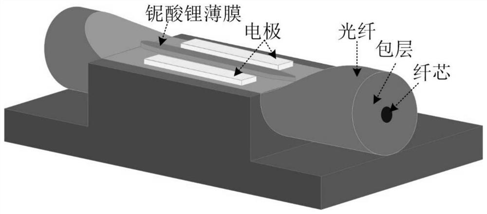
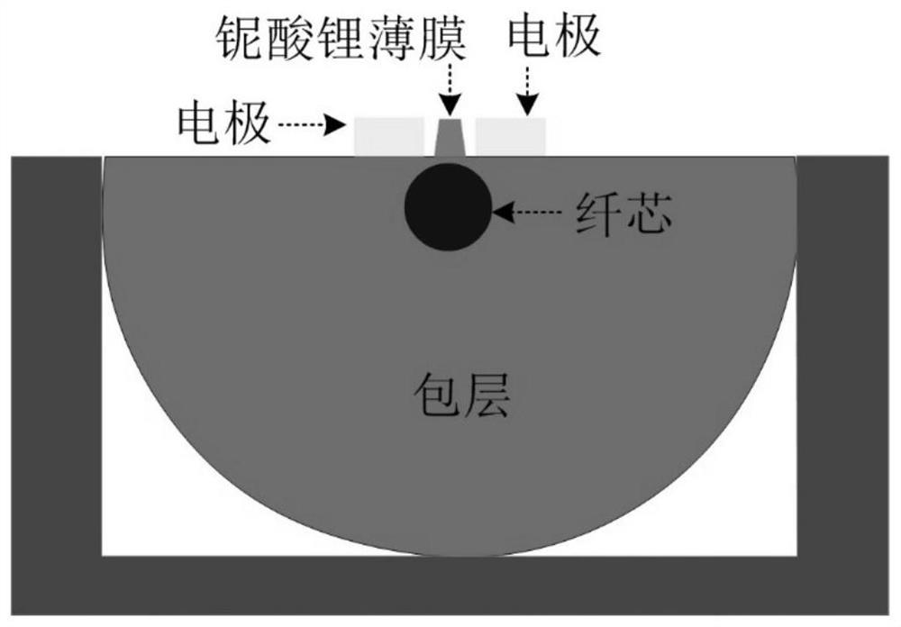
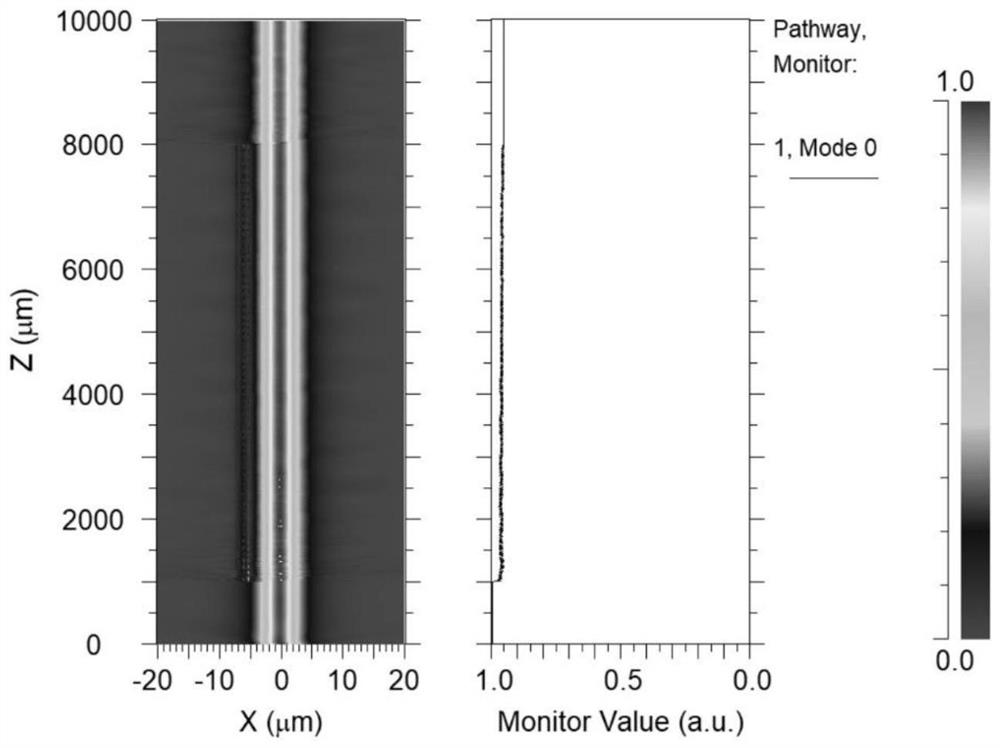
[0041] Such as figure 1 Shown is the first implementation of the modulator provided by the embodiment of the present invention, such as figure 2 As shown, the thin-film lithium niobate waveguide is located directly above the fiber core; image 3 As shown, by controlling the vertical distance between the thin-film lithium niobate waveguide and the fiber core, and the cross-sectional size of the thin-film lithium niobate waveguide, it can be realized that most of the input light is transmitted to the output end through the fiber core when no voltage is applied to the electrode. A small amount of input light enters the thin-film lithium niobate waveguide and is eventually lost; as Figure 4 As shown, when a certain voltage is applied to the electrodes, the refractive index of the thin-film lithium niobate waveguide increases, and the transmitted light field will be more coupled into the thin-film lithium niobate waveguide. The optical field coupled into the thin-film lithium n...

Embodiment 2

[0049] In addition to using the above figure 1 In addition to the structure, the novel optical fiber online modulator based on thin-film lithium niobate waveguide proposed by the present invention can also adopt Figure 5 Shown in the second implementation, such as Figure 6 As shown, the thin-film lithium niobate waveguide is arranged at a certain distance away from the axis directly above the fiber core.

[0050] exist Figure 5 In the illustrated structure, by controlling the waveguide cross-sectional size and waveguide length of the thin-film lithium niobate waveguide at the input end, the optical field energy in the fiber core at the input end is coupled into the thin-film lithium niobate waveguide according to a specific ratio. By adjusting the voltage applied to the electrodes, controlling the phase of the propagating light field in the thin-film lithium niobate waveguide, and using the principle of interference, the intensity modulation of the light signal can also b...

Embodiment 3

[0058] The novel optical fiber online modulator based on thin-film lithium niobate waveguide proposed by the present invention can also adopt Figure 7 The third implementation is shown.

[0059] Such as Figure 8 As shown, the thin-film lithium niobate waveguide is fabricated as an MZI structure, and by controlling the waveguide cross-sectional size and waveguide length of the input-end thin-film lithium niobate waveguide, all the light field energy in the input-end fiber core is coupled into the thin-film lithium niobate waveguide . The MZI structure has two branches, and the phases of the transmitted light fields in the two branches are regulated by the tuning electrodes respectively. The two branches merge into one at the end of the MZI structure. At this time, the light fields in the two branches interfere, and the interference can convert the change of phase into the change of intensity. Finally, the light in the waveguide is coupled back into the fiber core and outpu...


PUM


Abstract

The invention discloses a novel optical fiber online modulator based on lithium niobate thin film. Aiming at the problems of large insertion loss and poor stability existing in the existing electro-optic modulator, the modulator of the invention includes a transmission optical fiber, and the transmission optical fiber is divided into The three parts are recorded as the first part, the second part, and the third part in turn; the first part is the input fiber, the second part is the modulation area, and the third part is the output fiber; part of the cladding is removed from the transmission fiber in the modulation area, and Fabricate thin-film lithium niobate waveguides and tuning electrodes on the plane where part of the cladding is removed; using the electro-optical effect of lithium niobate, according to the phase change of the optical field propagating in the thin-film lithium niobate waveguide, or the change of the overall mode field distribution of the device, The modulation of the intensity of the final output optical signal is realized, and the online modulator of the present invention has the advantages of small device volume and stable performance.

Description

technical field [0001] The invention belongs to the field of optical communication, and in particular relates to the structure and function realization of a novel optical fiber online modulator based on lithium niobate thin film. Background technique [0002] In the era of information explosion, big data, Internet of Things, artificial intelligence and other technologies gradually penetrate into people's lives, and the diversity and complexity of information services make the transmission speed and capacity of communication systems more and more demanding. Optical fiber communication is far superior to cable and microwave communication due to its transmission frequency bandwidth, high anti-interference and low signal attenuation, and has become the main transmission mode in world communication. Optical fiber communication system mainly consists of two parts: transmission and switching. Due to the advantages of low transmission loss, strong anti-electromagnetic interference ...

Claims


Application Information

Patent Timeline
Patent Type & Authority Patents(China)
IPC IPC(8): G02F1/035
CPCG02F1/035
Inventor 陈开鑫兰涛明王梦柯李俊慧
Owner UNIV OF ELECTRONICS SCI & TECH OF CHINA
Learn More