Ultrahigh-speed revolving cup assembly directly driven by iron-loss-free permanent magnet brushless motor

A permanent magnet brushless motor, ultra-high-speed technology, applied in the direction of electric components, magnetic circuit rotating parts, electrical components, etc., can solve the problems of mechanical bearing wear, large mechanical friction loss, and large volume of bearing components, and achieve radial Small centrifugal force, reduced moment of inertia, and improved power density

Inactive Publication Date: 2020-04-10
武汉万至达智能科技有限公司 +1
View PDF10 Cites 0 Cited by
  • Summary
  • Abstract
  • Description
  • Claims
  • Application Information

AI Technical Summary

Problems solved by technology

At present, the conventional rotor drive method adopts the dragon belt drive, and its disadvantages are as follows: 1. The rotor cannot reach a high speed, usually within 120,000 rpm, and the energy consumption generated by continuing to increase the speed is unbearable; 2. The dragon belt transmission cannot achieve differentiated control of a single spindle, and it is inconvenient to maintain and install; 3. The dragon belt contacts the rotor shaft at high speed, causing high vibration and high noise, and the key parts need to be replaced regularly due to wear. The entire rotor part driven by the drive is large in size, which will inevitably cause high-speed centrifugal force to cause increased mechanical friction, resulting in high power loss
[0004] At the same time, at present, the direct drive scheme of the motor has been gradually introduced, which has greatly improved the various deficiencies of the belt drive to a certain extent, but the following problems still exist: 1. The use of mechanical contact bearings, and the rotor shaft Due to the limitation of structure and function, the diameter of the rod is still too large, resulting in excessive mechanical friction loss (according to the actual measurement, the loss of the shaft with a diameter of 9 mm is more than 45% higher than that of a shaft with a diameter of 6 mm), and some projects use external rotation bearings 2. The air bearing scheme is adopted, although it has a significant effect in reducing mechanical wear, but the noise caused by high-pressure airflow, and the laying of gas pipelines is also likely to cause messy spinning production lines, and The complexity of the air bearing causes the volume of the bearing assembly to be too large; 3. Adopt a brushless motor scheme with slots or no slots in the stator (iron core), and the iron core loss in the iron core has a great influence on the magnetic density and magnetic field change frequency Very sensitive, so the loss is still high; 4. The structure of the motor and its rotor expands in the "radial" direction, according to the formula of moment of inertia J=mR 2 It can be seen that it is unreasonable to adopt the "radial" expansion instead of "axial" expansion. The larger radial size increases the radial centrifugal force, which makes the mechanical bearing wear seriously or the air pressure power of the air bearing is increased; 5. The mechanical contact braking method is adopted. Under the condition of ultra-high speed (such as above 150,000 rpm), not only the noise and vibration are large, the parts are worn out, but also it is not conducive to safe production.

Method used


Image

  • Ultrahigh-speed revolving cup assembly directly driven by iron-loss-free permanent magnet brushless motor
  • Ultrahigh-speed revolving cup assembly directly driven by iron-loss-free permanent magnet brushless motor
  • Ultrahigh-speed revolving cup assembly directly driven by iron-loss-free permanent magnet brushless motor

Examples


Embodiment Construction

[0037]In order to make the object, technical solution and advantages of the present invention clearer, the present invention will be further described in detail below in conjunction with the accompanying drawings and embodiments. It should be understood that the specific embodiments described here are only used to explain the present invention, not to limit the present invention. In addition, the technical features involved in the various embodiments of the present invention described below can be combined with each other as long as they do not constitute a conflict with each other.

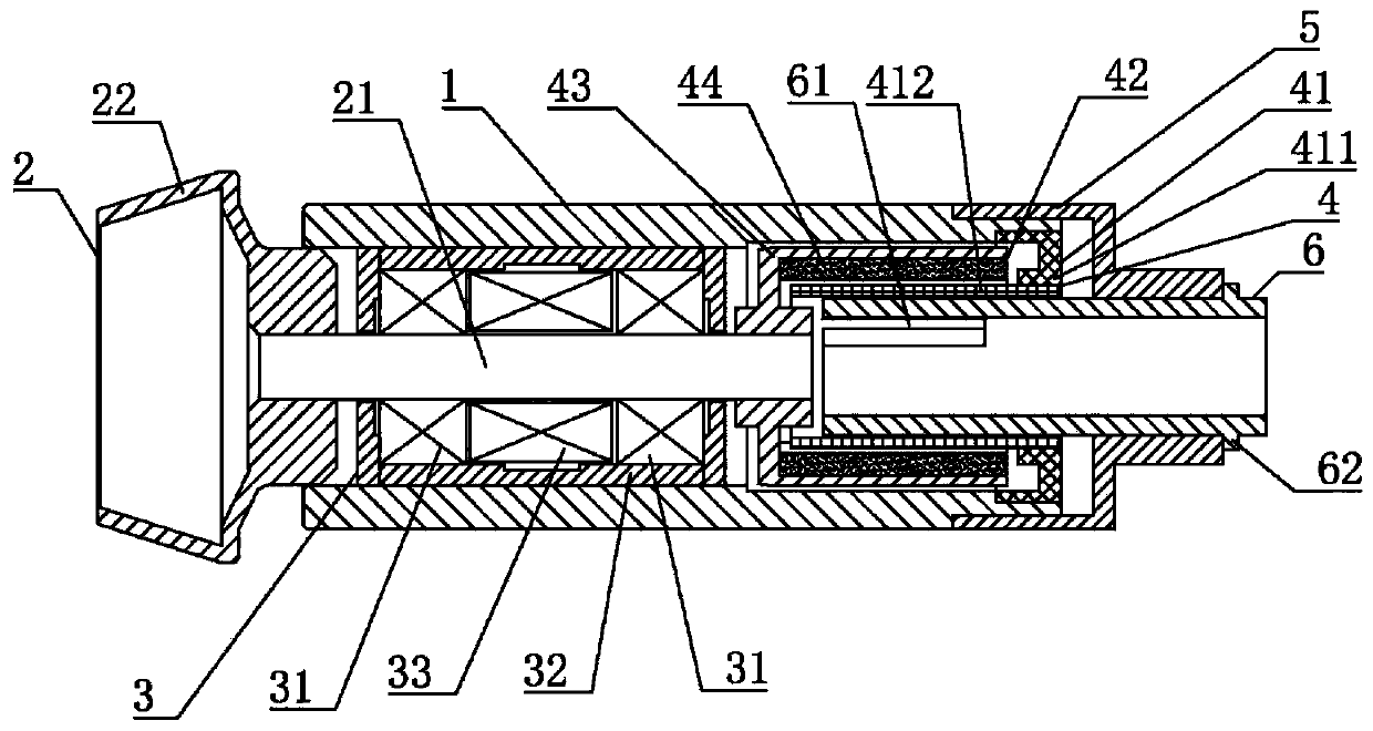
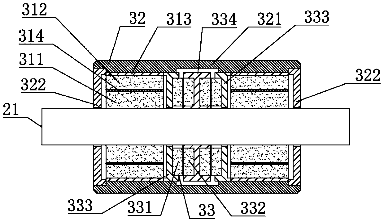
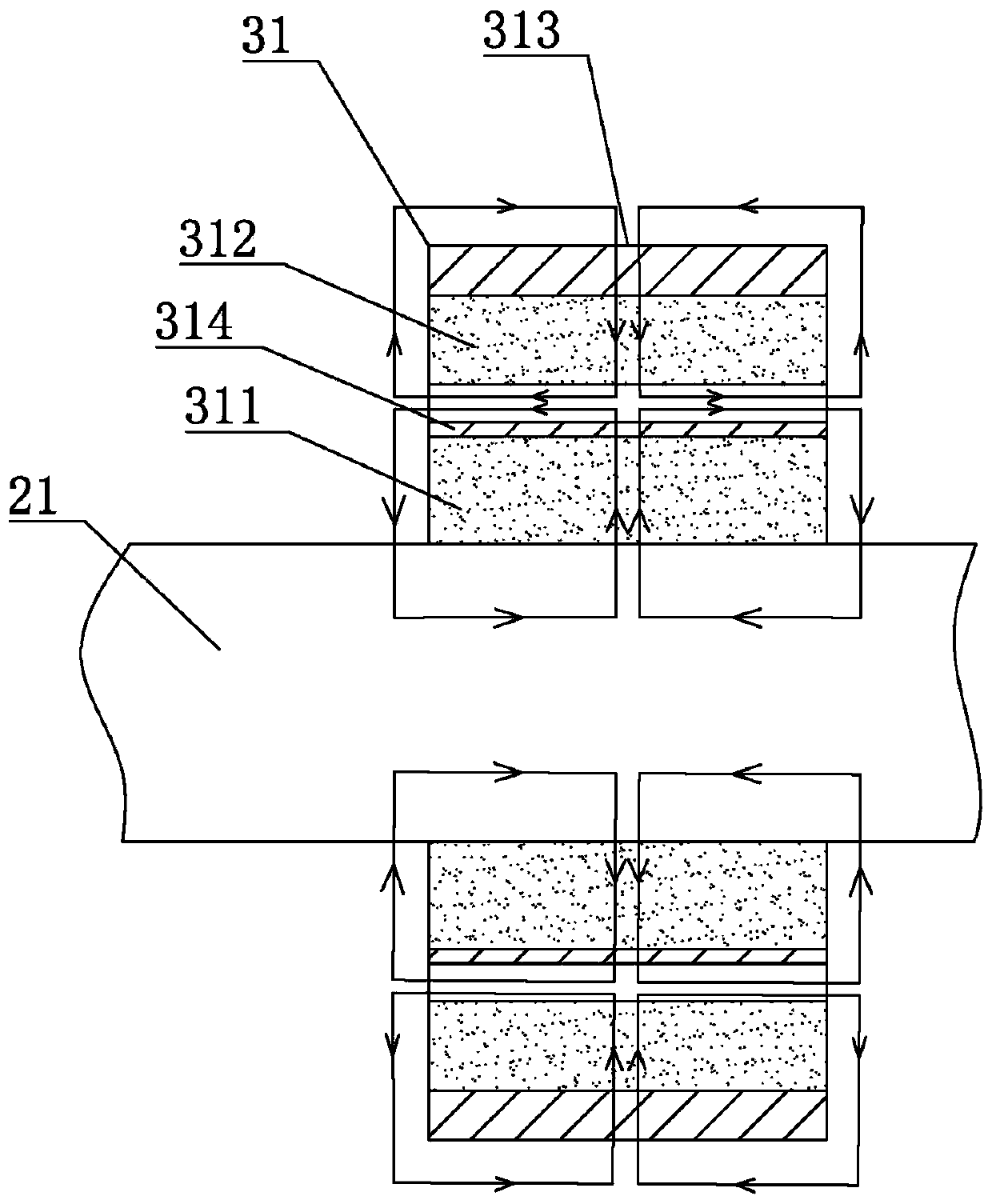
[0038] Such as Figure 1 to Figure 6 As shown, an ultra-high-speed rotor assembly directly driven by a permanent magnet brushless motor without iron loss, including a fixed sleeve 1, a rotating part 2, a permanent magnetic suspension bearing part 3 and a motor 4, wherein the fixed sleeve 1 is used as the installation of other parts the foundation, which is fixed against rotation, and,

[0039] ...


PUM


Abstract

The invention discloses an ultrahigh-speed revolving cup assembly directly driven by an iron-loss-free permanent magnet brushless motor, which comprises a fixed sleeve, a rotating part, a permanent magnet suspension bearing part and a motor, and is characterized in that the rotating part comprises a shaft rod and a revolving cup head; the permanent magnet suspension bearing part comprises a radialbearing, the radial bearing comprises an inner permanent magnet ring and an outer permanent magnet ring which are coaxially arranged, the outer permanent magnet ring is fixedly installed on the innerwall of the fixing sleeve, radial magnetization is adopted for the inner permanent magnet ring and the outer permanent magnet ring, and the polarity of the outer wall of the inner permanent magnet ring is the same as that of the inner wall of the outer permanent magnet ring; the motor comprises an armature assembly and a rotor assembly, the armature assembly is fixedly installed on the fixing sleeve, and the rotor assembly is fixedly connected with the shaft rod. A compact permanent magnet suspension bearing structure is adopted, so that a rotating component has smaller rotational inertia under the condition of the same mass, the radial centrifugal force of a rotor component is smaller, and the use amount of permanent magnets in the permanent magnet suspension bearing is reduced.

Description

technical field [0001] The invention belongs to the technical field of rotor spinning, and more specifically relates to an ultra-high-speed rotor assembly. Background technique [0002] my country is a traditional big textile country, but compared with traditional western textile powerhouses, although my country's textile industry is large in scale, the level of technical equipment is generally low, especially in terms of rotor spinning machines, which occupy an important position in mid-to-high-end spinning equipment. There is a big gap between textile equipment and foreign advanced technology. Rotor spinning is the most mature, fastest-growing and most widely used new spinning technology in textile technology. By 2017, China's rotor spinning spindles have reached more than 4 million, accounting for 51% of the world's total output. In recent years, foreign advanced spinning equipment providers have continued to develop in the high-speed, multi-spindle, and automation aspect...

Claims


Application Information

Patent Timeline
Patent Type & Authority Applications(China)
IPC IPC(8): H02K7/14H02K7/09H02K11/01H02K7/10H02K3/47H02K1/27
CPCH02K1/2786H02K3/47H02K7/09H02K7/10H02K7/14H02K11/01H02K2201/03H02K2203/12H02K2213/03
Inventor 胡佳翁孟坤吕高强张贝妮刘健
Owner 武汉万至达智能科技有限公司
Why Eureka
Try Eureka