Nitriding sintering furnace

A technology of nitriding sintering and furnace body, which is applied to furnaces, furnace types, furnace components, etc., can solve the problems of low safety, volume change of insulating materials, poor practical application effect, etc. The effect of ensuring accuracy and improving safety

Inactive Publication Date: 2020-05-01
HANJIANG HONGYUAN XIANGYANG SILICON CARBIDE SPECIAL CERAMICS
View PDF0 Cites 0 Cited by
  • Summary
  • Abstract
  • Description
  • Claims
  • Application Information

AI Technical Summary

Problems solved by technology

[0003] The furnace door of the existing nitriding sintering furnace is a double-layer steel plate welded structure, and the temperature in the nitriding sintering furnace is relatively high. When the materials in the kiln car are sintered, due to the heat preservation and sealing between the kiln car and the furnace body The effect is not good, and the temperature of the furnace door is easy to rise. In order to prevent the temperature of the furnace door from being too high, a water-cooling structure is installed between the double-layer steel plates of the furnace door to cool the furnace door through water circulation. However, when the water-cooling structure runs If there is a fault or accidental water stoppage without timely detection, the water located between the double-layer steel plates will be heated and boiled, vaporized, and the volume will expand hundreds of times at the same time, which is less safe, and some water vapor will pass through the partition in the furnace door The hot

Method used


Image

  • Nitriding sintering furnace
  • Nitriding sintering furnace

Examples


Embodiment Construction

[0022] The technical solutions in the embodiments of the present invention will be clearly and completely described below in conjunction with the drawings in the embodiments of the present invention. Apparently, the described embodiments are only some of the embodiments of the present invention, not all of them. Based on the embodiments of the present invention, all other embodiments obtained by persons of ordinary skill in the art without creative efforts fall within the protection scope of the present invention.

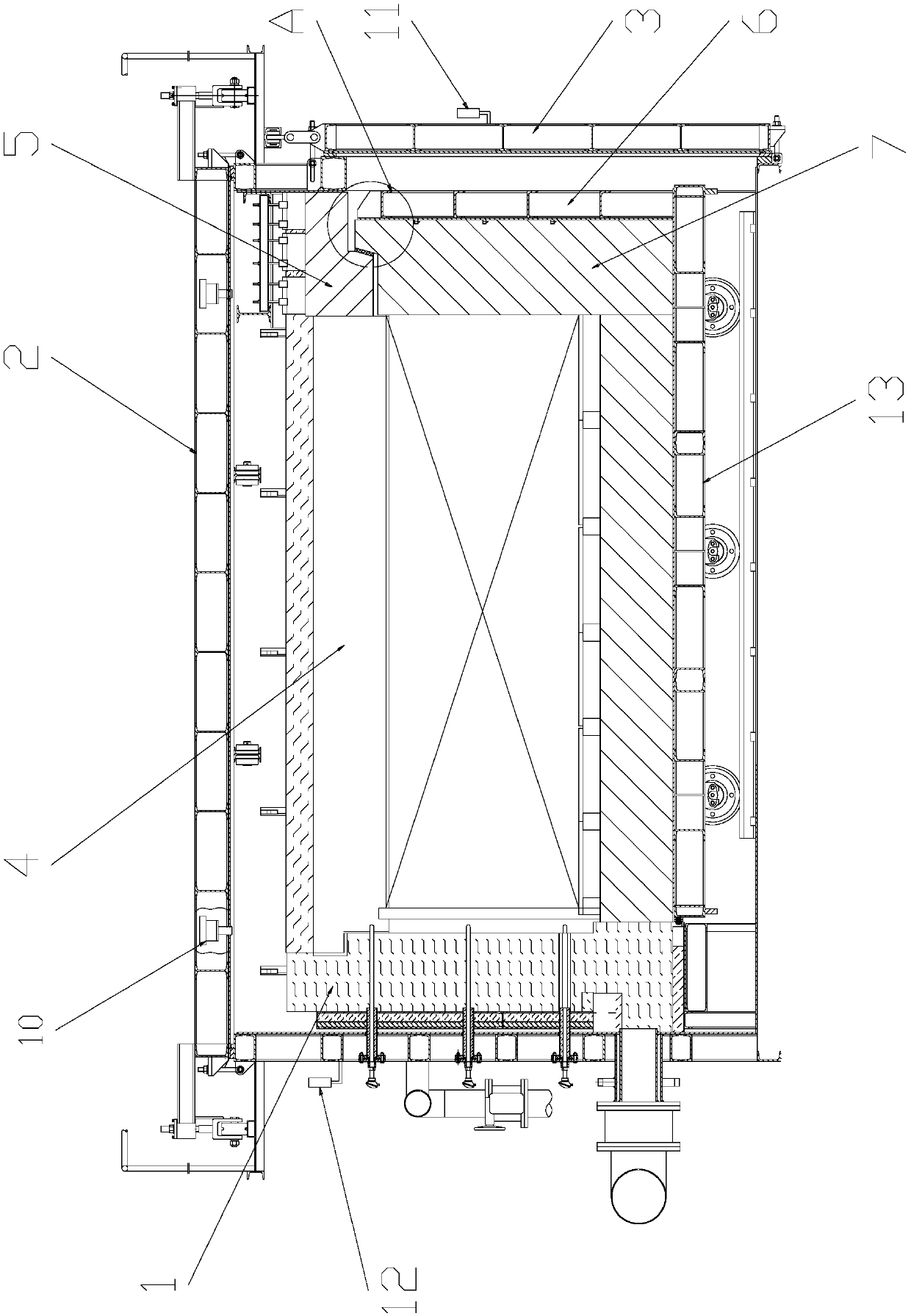
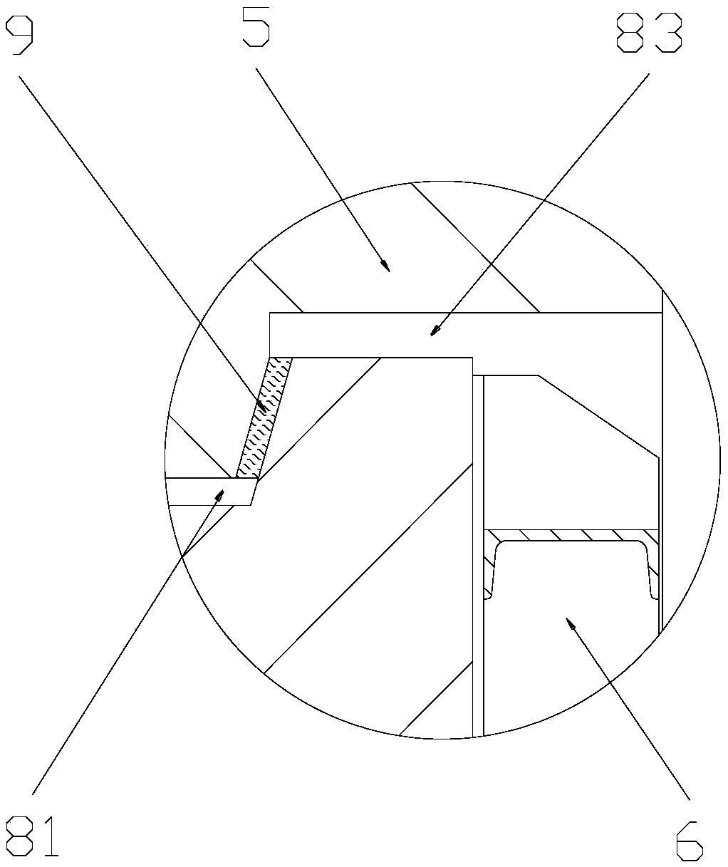
[0023] Such as figure 1 , figure 2 As shown, a nitriding sintering furnace includes a furnace body 1 provided with a nitriding chamber 4, a furnace cover 2, a kiln car 13 that can enter and exit the nitriding chamber 1, and a furnace door 3 for closing the furnace body 1. The furnace body 1 is provided with a heat insulation layer 5, and the side wall on the kiln car 13 used to close the nitriding chamber 4 is a composite structure, and the composite structure i...


PUM


Abstract

The invention belongs to the technical field of industrial kilns, and particularly relates to a nitriding sintering furnace. The nitriding sintering furnace comprises a furnace body provided with a nitriding chamber, a furnace cover, a kiln car capable of entering and exiting the nitriding chamber and a furnace door used for closing the furnace body; a heat insulation layer is arranged in the furnace body; the side wall, for closing the nitriding chamber, of the kiln car is of a composite structure; the composite structure comprises a steel structure layer and a refractory brick layer arrangedon one side, close to the nitriding chamber, of the steel structure layer; a heat insulation channel is formed between the heat insulation layer and the refractory brick layer and comprises a first channel, a second channel and a third channel; the first channel, the second channel and the third channel sequentially communicate from bottom to top; and the second channel is obliquely arranged andis filled with a heat insulation medium. According to the nitriding sintering furnace, tight filling of the heat insulation medium between the kiln car and the furnace body can be ensured during sintering each time, so that the continuous heat insulation effect is ensured, and the furnace door is prevented from overheating.

Description

technical field [0001] The invention belongs to the technical field of industrial furnaces, in particular to a nitriding sintering furnace. Background technique [0002] Nitriding sintering furnace is the core production equipment for producing silicon nitride bonded silicon carbide ceramics, boron nitride, pure silicon nitride, nitride alloy and other products. For example, the mixture of silicon carbide particles and metal silicon powder, after pressing or casting, is placed in a nitriding sintering furnace, and is nitrided and fired in a nitrogen atmosphere at about 1400°C, which can be made into a material with high temperature strength and thermal conductivity. Silicon nitride bonded silicon carbide ceramics with high efficiency, good thermal shock resistance, high load softening point, low thermal expansion coefficient, and high temperature creep resistance. [0003] The furnace door of the existing nitriding sintering furnace is a double-layer steel plate welded stru...

Claims


Application Information

Patent Timeline
IPC IPC(8): F27B17/00F27D1/00F27D21/00F27D21/02
CPCF27B17/00F27D1/0033F27D21/00F27D21/02F27D2021/0007F27D2021/0071
Inventor 王惠民李秋南夏志强吴急涛黄涛张汉义
Owner HANJIANG HONGYUAN XIANGYANG SILICON CARBIDE SPECIAL CERAMICS
Why Eureka
Try Eureka