
Surface treatment method for fiber reinforced composite material

A composite material and surface treatment technology, applied in cleaning methods and utensils, chemical instruments and methods, etc., can solve the problems of low repetition rate, high cost, low efficiency, etc., to improve the bonding strength, achieve the effect of cleaning and activation

Inactive Publication Date: 2020-06-05
TIANJIN UNIV
View PDF10 Cites 3 Cited by
  • Summary
  • Abstract
  • Description
  • Claims
  • Application Information

AI Technical Summary

Problems solved by technology

[0004] However, most of the existing commercial ultrashort pulse lasers use amplification systems to achieve the power required for industrial production. The repetition rate is generally low (less than 1MHz), the cost is high, the structure is complex, and the efficiency is low. This has become the industry application of ultrashort pulse lasers. the bottleneck
However, the long-pulse laser processing technology that has been maturely applied in the industry cannot meet the needs of practical applications due to thermal effects.

Method used


Image

  • Surface treatment method for fiber reinforced composite material

Examples


Embodiment 1

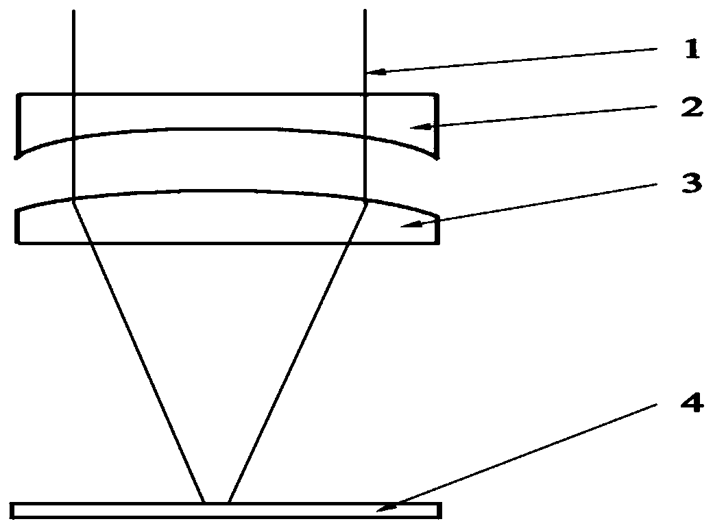
[0022] The embodiment of the present invention provides a method for surface treatment of fiber reinforced composite materials, see figure 1 , the method includes the following steps:

[0023] 1. Adjust two laser beams (femtosecond laser and nanosecond laser) to combine beams.

[0024] Select a beam of ultrashort pulse laser and a beam of nanosecond laser (both have the same pulse repetition frequency and wavelength) as the laser source, and combine the beams. In actual implementation, adjust the laser beam perpendicular to the sample according to the position of the sample surface in the actual application. surface.

[0025] Wherein, the laser wavelength is in the visible or infrared band. The ultrashort pulse laser usually has a pulse width of the order of femtoseconds, and the embodiment of the present invention does not limit the process of laser beam combining and collimation device adjustment.

[0026] 2. Homogenize the beam intensity of the combined laser beam 1

[...

Embodiment 2

[0032] The scheme in embodiment 1 is further introduced below in conjunction with specific examples, see the following description for details:

[0033] Install the sample 4 on the workbench or the displacement stage, and then select a beam of ultrashort pulse laser and a beam of nanosecond laser (with the same pulse repetition frequency and wavelength) as the laser source, combine the beams, and then pass through the beam shaping element 2 After homogenizing the light intensity, it converges vertically to the surface of sample 4.

[0034] The ultrashort pulse laser adopts a pulse width of 10-10000 femtoseconds, a repetition frequency of 0.001-50MHz, and a power of 1-100W. When the ultrashort pulse laser intensity is greater than or equal to the multiphoton absorption threshold light intensity on the surface of the composite material, multiphoton absorption occurs on the surface of sample 4 within the laser irradiation range, and the nanosecond laser energy is absorbed until t...


PUM


Abstract

The invention discloses a surface treatment method for a fiber reinforced composite material. The surface treatment method comprises the following steps that one beam of ultra-short pulse laser and one beam of nanosecond laser are selected as laser sources, beam combing are carried out, the two beams of laser are with the same pulse repetition frequency and wavelength, and then the two beams of laser vertically converge to the surface of a sample after being subjected to light intensity homogenization through a beam shaping element; when the ultra-short pulse laser intensity is greater than orequal to the multi-photon absorption threshold light intensity of the surface of the composite material, multi-photon absorption occurs on the surface of the sample in a laser irradiation range, andwhen the nanosecond laser energy is absorbed until an ablation threshold is reached, a surface thin layer of the sample is removed, so that the surface of the sample is cleaned and activated; and theentire surface of the sample is treated as the laser scans along a pre-designed route and a displacement table moves in cooperation. The surface treatment method for the fiber reinforced composite material removes impurity contaminants (such as a release agent on the surface of a part) on the surface of the fiber reinforced composite material, and activates the surface, so that effective chemicalbonding is realized.

Description

technical field [0001] The invention relates to the field of surface treatment of composite materials, in particular to a method for surface treatment of fiber-reinforced composite materials. Background technique [0002] Carbon fiber reinforced composite materials have low density, ultra-high specific strength and stiffness, and have been relatively maturely applied in the aerospace field. The bonding technology between carbon fiber reinforced composite parts requires pretreatment of the surface of the parts to remove impurity contaminants (release agent on the surface of the parts), clean the surface, improve surface polarity, and increase surface energy, that is, improve wettability and surface tension and activates the surface for effective bonding. [0003] Applying laser cleaning technology to the surface treatment of carbon fiber composites can greatly improve the surface quality of carbon fiber composites and improve the quality of parts bonding / welding processing. ...

Claims


Application Information

Patent Timeline
Patent Type & Authority Applications(China)
IPC IPC(8): B08B7/00B29C65/00
CPCB08B7/0042B29C65/00B29C66/028B29C66/721
Inventor 贾威于俭刘博文柴路胡明列
Owner TIANJIN UNIV
Learn More