
Method for suppressing generation of metal steam and photoinduced plasma

A plasma and metal vapor technology, used in metal processing equipment, manufacturing tools, laser welding equipment, etc., to achieve the effect of improving welding quality

Inactive Publication Date: 2020-06-05
XIAMEN UNIV OF TECH
View PDF4 Cites 0 Cited by
  • Summary
  • Abstract
  • Description
  • Claims
  • Application Information

AI Technical Summary

Problems solved by technology

[0008] The present invention provides a method for suppressing the generation of metal vapor and photoplasma, aiming to improve the problem that the existing welding method requires additional supporting devices to eliminate part of the metal vapor and photoplasma that have been produced in large quantities

Method used


Image

  • Method for suppressing generation of metal steam and photoinduced plasma
  • Method for suppressing generation of metal steam and photoinduced plasma
  • Method for suppressing generation of metal steam and photoinduced plasma

Examples


Embodiment

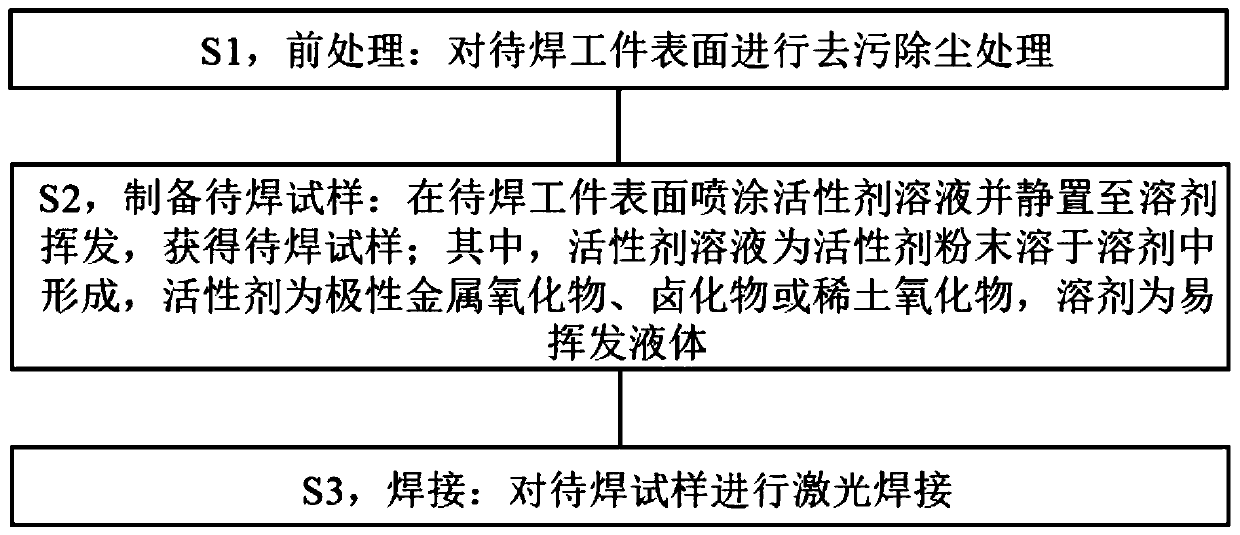
[0040] refer to figure 2 As shown, the embodiment of the present invention provides a method for suppressing the generation of metal vapor and photoinduced plasma, carried out in the laser welding test system, including the following steps:

[0041] S1, pretreatment: decontamination and dust removal on the surface of the workpiece to be welded.

[0042] In this embodiment, in order to remove stains and dust and ensure welding quality, it is necessary to perform surface treatment on the workpiece to be welded during laser welding. Optionally, the surface of the workpiece to be welded can be wiped with volatile solvents such as acetone and ethanol to remove oil-immersed dust; the workpiece to be welded can also be pickled, washed with water, etc. to remove impurities on the surface of the workpiece to be welded and then dried. Invention is not limited.

[0043] Further, in a preferred embodiment of the present invention, in this step, the step of decontaminating and dust-remo...

Embodiment 1

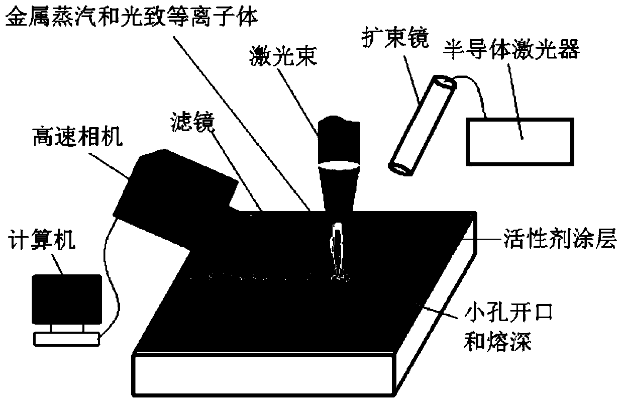
[0061] see Figure 5 As shown, prepare 100×50×8mm stainless steel as the workpiece to be welded, and wipe the surface of the workpiece to be welded with acetone to remove oil immersion dust.

[0062] Weighing Cr with precision electronic scale 2 o 3 Active agent, measure the acetone solution with a measuring cup, and add Cr 2 o 3 The active agent is dissolved in acetone solution to prepare a supersaturated solution. Put the above supersaturated solution into the coating cup of the micro-spray gun, start the air compressor, adjust the gas flow, control the spraying distance and spraying range, spray the active agent solution evenly on the surface of the workpiece to be welded by the micro-spray gun, and the spraying is completed Finally, let the workpiece to be welded stand until the acetone is completely volatilized to make a sample to be welded. Among them, the spraying amount is controlled at 0.05-0.1g / cm 2 .

[0063] After the sample is clamped, a fiber laser is used...


PUM


Abstract

The invention provides a method for suppressing generation of metal steam and photoinduced plasma, and relates to the technical field of laser welding. The method comprises the following steps of S1,pretreatment, wherein dirt removal and dust removal treatment is carried out on the surface of a to-be-welded workpiece; S2, preparing of a to-be-welded sample, wherein an active agent solution is sprayed to the surface of the to-be-welded workpiece, standing is carried out till a solvent is volatilized, the to-be-welded sample is obtained, the active agent solution is formed by dissolving activeagent powder in the solvent, the active agent is formed by polar metal oxide, halide or rare earth oxide, and volatile liquid serves as the solvent; and S3, welding, wherein the to-be-welded sample issubjected to laser welding. According to the method, the active agent solution is sprayed to the surface of the to-be-welded workpiece, and therefore the problem of generation of metal steam and photoinduced plasma in the laser welding process can be suppressed from the source.

Description

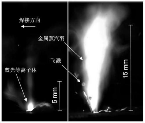
technical field [0001] The invention relates to the technical field of laser welding, in particular to a method for suppressing the generation of metal vapor and photoinduced plasma. Background technique [0002] Such as figure 1 As shown, under high-power-density laser beam irradiation, the rate of laser energy action is much greater than the rate of heat conduction, convection and heat radiation of the material, which makes the surface of the metal material evaporate and vaporize locally, forming metal vapor. Then, the metal vapor is further ionized under the action of high energy density laser to form photoplasma. Metal vapor and photoplasma have attenuation effects on the propagation of incident laser light, such as scattering, reflection and defocusing, which affect the absorption of laser energy by materials. At the same time, the violent eruption of metal vapor and photo-induced plasma affects the stability of small holes and molten pools during laser welding, which...

Claims


Application Information

Patent Timeline
IPC IPC(8): B23K26/60B23K26/21B23K26/70
CPCB23K26/21B23K26/60B23K26/702
Inventor 梅丽芳严东兵谢顺雷智钦
Owner XIAMEN UNIV OF TECH
Learn More