
Gas recovery/concentration device

A gas and recovery method technology, which is applied in the field of temperature swing adsorption carbon dioxide recovery and concentration devices, can solve the problems of high gas pressure loss, difficult to enlarge, and cannot ignore the operating cost, and achieves the effect of improving the recovery rate

Active Publication Date: 2020-06-12
SEIBU GIKEN CO LTD
View PDF15 Cites 6 Cited by
  • Summary
  • Abstract
  • Description
  • Claims
  • Application Information

AI Technical Summary

Problems solved by technology

In a multi-tower type in which multiple adsorption towers filled with carbon dioxide adsorbents alternately switch between adsorption and regeneration, the pressure loss of the gas is high, and there are unavoidable fluctuations in concentration and pressure caused by switching towers, making it difficult to large-scale Chemical defects
Also, although the waste heat can be used, there is a problem that the running cost cannot be ignored due to the use of the valuable waste heat that can also be converted into steam power
However, it is not sufficient in the recovery rate of carbon dioxide, concentration concentration, and energy saving of recovered energy.

Method used


Image

  • Gas recovery/concentration device
  • Gas recovery/concentration device
  • Gas recovery/concentration device

Examples


Embodiment 1

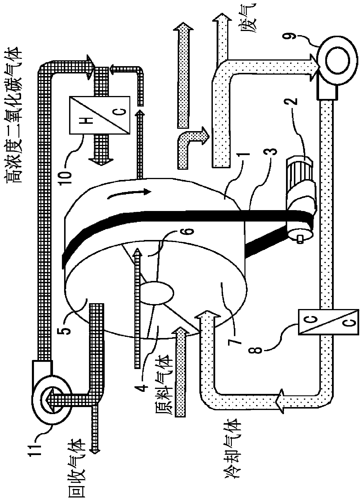
[0096] Image 6 The horizontal type of Example 1 is shown in. Regarding the honeycomb rotor 12, the following sheet material was corrugated to a pitch of 3.0 mm and a height of 2.0 mm, and it was wound into a rotor to obtain a volume specific gravity of 150 kg / m containing 50% by weight of solid amine particles 3 The honeycomb rotor 12, the sheet is 30-40g / m with inorganic fibers such as glass fiber as the main body 2 The porous paper is coated with a coating solution containing solid amine particles with a particle size distribution of 0.02 to 0.1 mm and a heat-resistant and water-resistant binder and dried.

[0097] The carbon dioxide recovery and concentration device equipped with the rotor 12 is provided with an adsorption zone 13 and a desorption zone 14. The honeycomb rotor 12 is configured to return from the adsorption zone 13 to the adsorption zone 13 through the desorption zone 14.

[0098] If the raw material gas after denitrification, desulfurization, dust removal, and co...

Embodiment 2

[0103] Figure 7 The vertical embodiment 2 is shown in. The honeycomb absorbing carbon dioxide moves to the desorption zone 14 through the rotation of the rotor. In the desorption zone, a circulation loop connecting the inlet and the outlet is formed, and a blower and a heat exchanger are installed in the loop, and a temperature-regulating heater as a gas heater is installed in the back section. The waste heat such as exhaust gas and hot water passes through the high temperature side of the heat exchanger.

[0104] The gas containing carbon dioxide as the main component in the low-temperature circulation circuit is circulated by a blower, and water is supplied to the low-temperature side of the heat exchanger using a sprayer, and the water film generated on the heat transfer surface is heated and evaporated to become saturated vapor containing gas. In addition, heating is performed by a temperature-regulating heater in the subsequent stage, and the relative humidity is slightly ...

Embodiment 3

[0106] Figure 8 Example 3 is shown in. The flue gas is processed for denitrification, desulfurization, and dust removal to obtain the raw material gas, but the gas is kept at a temperature close to 100°C and the dew point temperature. It has a structure in which the source gas side desorbs and regenerates the high temperature side of the saturated steam generating heat exchanger, and then cools and dehumidifies the high temperature side of the cooling and dehumidification heat exchanger, and exhausts gas by adsorbing the rotor with carbon dioxide.

[0107] The low temperature side of the heat exchanger for generating desorption and regeneration saturated steam constitutes a circulation loop of the inlet and outlet of the carbon dioxide adsorption rotor regeneration and desorption side and the blower. The gas with carbon dioxide as the main component in the circuit is circulated through a blower. If water is supplied to the low temperature side heat exchanger, the water film form...


PUM

PropertyMeasurementUnit
volume ratioaaaaaaaaaa

Abstract

[Problem] The present invention relates to a thermal swing carbon dioxide recovery / concentration device which is a honeycomb-rotor recovery / concentration device for recovering carbon dioxide gas fromflue gas or the like, the device having a high recovery rate, being capable of achieving high concentration, being small-sized and capable of utilizing waste heat of 100 DEG C or less, making it possible to reduce the amount of energy for recovery / concentration, and having high durability. [Solution] A device in which a carbon dioxide sorption honeycomb rotor is rotated in a casing which is divided into at least a sorption zone and a desorption zone in a sealed manner. In a state in which a honeycomb in the sorption zone is moist, a raw material gas including carbon dioxide is contacted to cause sorption of carbon dioxide gas. In the desorption zone, saturated vapor is contacted to cause desorption of carbon dioxide gas to recover carbon dioxide gas. While gas in a desorption circulation circuit is being circulated, water is supplied to a heater in the circuit and evaporated, and a saturated vapor including the gas is supplied to the desorption zone. The configuration makes it possibleto utilize low-temperature exhaust heat, and achieve size reduction, high performance, and high efficiency at the same time.

Description

Technical field [0001] The present invention relates to a temperature swing adsorption carbon dioxide recovery and concentration device, which recovers with a high recovery rate, can be concentrated to a high concentration, can be miniaturized, has high durability, can use waste heat below 100°C, and consumes less energy. Background technique [0002] As a countermeasure to global warming, the world is striving to reduce carbon dioxide emissions from industries, automobiles and users as much as possible. For example, it is promoting the development of energy-saving equipment and the development of renewable energy sources such as sunlight and wind. In addition, in the power generation relationship, technologies to improve the power generation efficiency of thermal power plants are developed, and in the future, technologies to recover and concentrate carbon dioxide emitted from thermal power plants and store them in the underground or deep sea will also be developed. [0003] Among...

Claims


Application Information

Patent Timeline
Patent Type & Authority Applications(China)
IPC IPC(8): B01D53/06B01D53/62B01D53/83B01D53/96
CPCB01D53/06B01D2258/0283B01D2257/504B01D2253/206B01D53/0462B01D2259/4009B01D53/025B01D53/62B01D53/96B01D2253/108B01D2253/3425B01D2257/80
Inventor 冈野浩志
Owner SEIBU GIKEN CO LTD
Learn More