Washing treatment system for silicon tetrafluoride in fluorine-containing tail gas

A silicon tetrafluoride and treatment system technology, applied in the field of washing and treatment systems, can solve the problems of system equipment blockage, the exhaust gas emission index cannot meet the limit requirements, and the technical difficulty is large, so as to save costs, improve the exhaust gas purification capacity and circulation. Recycling capacity, the effect of increasing the number of gas scrubbing stages

Pending Publication Date: 2020-06-19
福建易宏环保工程技术有限责任公司
View PDF0 Cites 0 Cited by
  • Summary
  • Abstract
  • Description
  • Claims
  • Application Information

AI Technical Summary

Problems solved by technology

[0004] At present, the tail gas washing and absorption processes in phosphoric acid production and phosphoric acid concentration process have been reported, including water washing, lime water washing, quicklime powder and activated carbon dry method to treat fluorine-containing tail gas; among them, water washing process is relatively simple, mature technology and widely used. The wet-process phosphoric acid workshop mostly adopts the two-stage countercurrent washing mode of "monofluorine scrubbing and absorption tower + difluorine scrubbing and absorption tower". Using this scrubbing mode to treat tail gas with high silicon tetrafluoride content has the following problems: First, the scrubbing mode H 2 SiF 6 After the solution is continuously circulated to wash and absorb fluorine-containing tail gas, it is easy to produce scales such as fluorosilicate and silica gel in the fluorine absorption system, causing the problem of system equipment blockage; secondly, with the H 2 SiF 6 With the gradual increase of solution concentration, the gas-liquid mass transfer rate decreases, resulting in poor exhaust gas washing and absorption effect, so that the exhaust gas emission indicators (particulate matter emission concentration, particle emission rate, fluoride emission concentration and fluoride emission rate) usually cannot meet the "air pollution The requirements of the secondary standard limit value of the comprehensive discharge standard of pollutants (GB16297-1996); third, silicon tetrafluoride is absorbed by water to form low-concentration fluorosilicic acid, and low-concentration H 2 SiF 6 Direct production of Na 2 SiF 6 Or anhydrous HF technology is more difficult and the production cost is higher

Method used


Image

  • Washing treatment system for silicon tetrafluoride in fluorine-containing tail gas
  • Washing treatment system for silicon tetrafluoride in fluorine-containing tail gas
  • Washing treatment system for silicon tetrafluoride in fluorine-containing tail gas

Examples


Embodiment 1

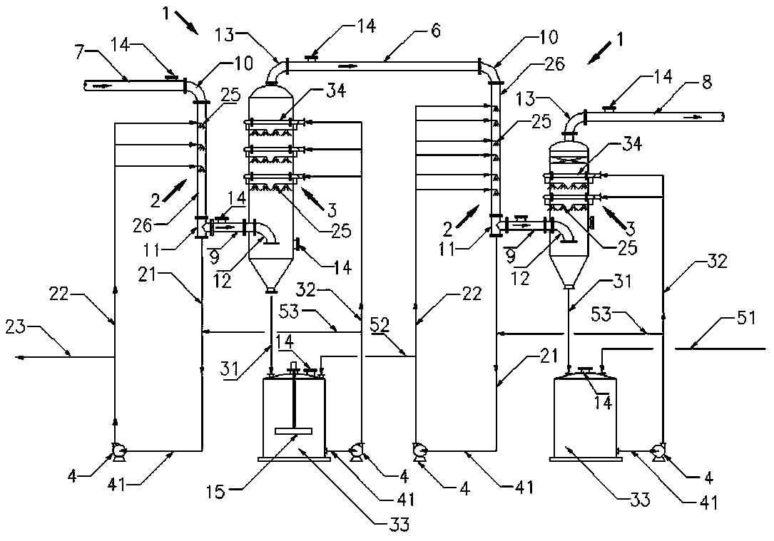
[0048] see figure 1 , a scrubbing system for silicon tetrafluoride in fluorine-containing tail gas, comprising two sets of interconnected scrubbing and absorbing devices 1; each scrubbing and absorbing device 1 includes interconnected scrubbers 2 and fluorine absorbing towers 3; the previous scrubbing The air inlet of the scrubber 2 of the absorption device 1 communicates with the fluorine-containing tail gas inlet pipe 7, and the gas outlet of the fluorine absorption tower 3 of the latter scrubbing and absorption device 1 communicates with the purified tail gas outlet pipe 8; the fluorine-containing tail gas inlet pipe 7 The initial tail gas purification is performed by connecting the scrubber intake elbow 10 with the air inlet at the top of the scrubber 2, and the two ends of the scrubber intake elbow 10 are respectively connected to the end of the fluorine-containing exhaust gas intake pipe 7 and the top of the scrubber 2 The inlet flange is connected; the purified tail gas...

Embodiment 2

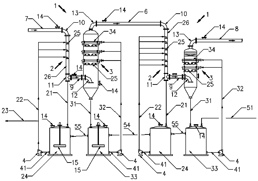
[0058] see figure 2 , the connection mode of two sets of washing and absorbing devices 1 in embodiment 2 is basically the same as that of the two sets of washing and absorbing devices 1 in embodiment 1, the difference is that in embodiment 2, the bottom of tube scrubber 26 is connected A second circulation tank 24 is also connected in series between the atmospheric leg 21 of the scrubber and the liquid inlet pipe 41 of the circulation pump, and the bottom of the tubular scrubber 26 is connected to the liquid inlet at the top of the second circulation tank 24 through the atmospheric leg 21 of the scrubber , the liquid outlet of the second circulation tank 24 communicates with the liquid inlet of the circulation pump 4 through the liquid inlet pipe 41 of the circulation pump, and the liquid outlet of the circulation pump 4 is connected to the tubular washing machine through the liquid inlet pipe 22 of the washer and its branch pipe. The liquid inlet of the spray device 25 on th...

Embodiment 3

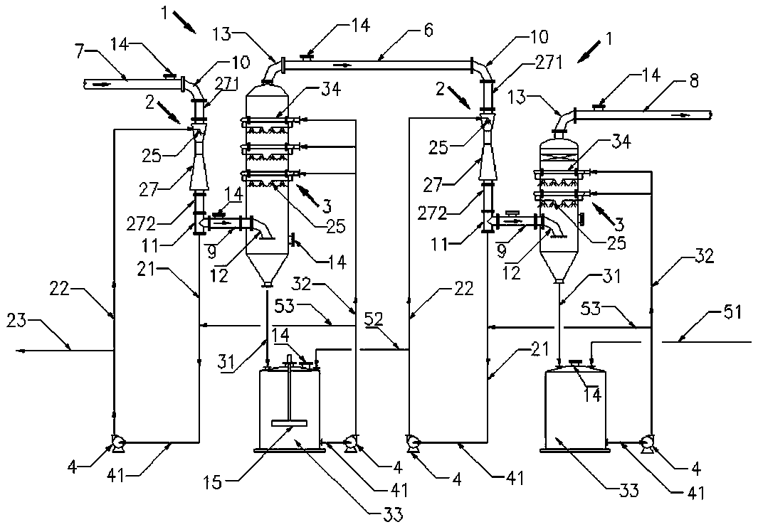
[0061] see image 3 , the connection mode of two sets of washing and absorbing devices 1 in embodiment 3 is basically the same as that of the two sets of washing and absorbing devices 1 in embodiment 1, the difference is that the scrubbers 2 in the two washing and absorbing devices 1 are Venturi Scrubber 27; the top inlet of the Venturi scrubber 27 communicates with the fluorine-containing tail gas inlet pipe 7 through the inlet pipe 271, and the bottom gas outlet communicates with the scrubber atmospheric leg 21 through the outlet pipe 272.


PUM


Abstract

The invention provides a washing treatment system for silicon tetrafluoride in fluorine-containing tail gas. The washing treatment system comprises two sets of washing absorption devices which are communicated with each other, each set of washing absorption device comprises a washer and a fluorine absorption tower which are communicated with each other, the fluorine absorption tower of the previous washing absorption device is communicated with the washer of the latter washing absorption device, the gas inlet of the washer of the previous washing absorption device is communicated with the fluorine-containing tail gas inlet pipe, and the gas outlet of the fluorine absorption tower of the latter washing absorption device is communicated with the purified tail gas outlet pipe; the washer andthe fluorine absorption tower are respectively provided with a washing liquid circulation loop; the washing liquid circulation loop of the washer in the previous washing absorption device is connectedwith a finished fluosilicic acid outlet pipe for discharging fluosilicic acid, and the washing liquid circulation loop of the fluorine absorption tower in the latter washing absorption device is provided with a first washing liquid supplementing pipe for inputting washing liquid to the outside; the two washing absorption devices and the washer and the fluorine absorption tower of each washing absorption device are communicated with each other through a liquid supplementing pipe network for supplementing washing liquid.

Description

technical field [0001] The invention relates to a washing treatment system for silicon tetrafluoride in fluorine-containing tail gas, belonging to the technical field of tail gas treatment. Background technique [0002] In the production of wet-process phosphoric acid and the concentration of phosphoric acid, because the phosphate rock used contains fluorine, a large amount of fluorine-containing compounds will be produced during the reaction, among which silicon tetrafluoride has a high content and escapes into the tail gas scrubbing system in the form of gas , is the main environmental pollutant, in order to reduce environmental pollution and achieve the purpose of comprehensive utilization, it must be recycled. [0003] Silicon tetrafluoride, also known as silicon fluoride, has the molecular formula SiF 4 , is a colorless, poisonous, irritating odor gas, easy to deliquescence, can produce dense smoke in humid air, human body can cause headache, nausea and different degre...

Claims


Application Information

Patent Timeline
Patent Type & Authority Applications(China)
IPC IPC(8): B01D53/68B01D53/78B01D53/75B01D53/96
CPCB01D53/68B01D53/75B01D53/78B01D53/96B01D2257/55
Inventor 洪铭阳
Owner 福建易宏环保工程技术有限责任公司
Why Eureka
Try Eureka