
Coating method for improving ionic conductivity of positive electrode material of lithium ion battery and coated and modified positive electrode material

A technology for lithium-ion batteries and positive electrode materials, which is applied to battery electrodes, cylindrical shell batteries/batteries, positive electrodes, etc. It can solve the problems of affecting the ion conductivity of positive electrode materials and unspecific conduction of lithium ions, so as to suppress side reactions , Improve lithium ion conductivity, improve the effect of rate performance

Inactive Publication Date: 2020-06-26
SAIC MOTOR
View PDF5 Cites 10 Cited by
  • Summary
  • Abstract
  • Description
  • Claims
  • Application Information

AI Technical Summary

Problems solved by technology

[0003] The existing coating technology generally adopts coprecipitation, sol-gel, thermal sintering and other methods to coat a layer of passive oxides such as alumina, magnesium oxide, titanium dioxide, silicon dioxide, etc. on the surface of the material. It is difficult to uniformly form a network structure coating on the surface of the material, and most of them are covered with an island structure (see Chinese patent CN102315430A "A Metal Oxide Coated Cathode Material for Lithium-ion Batteries")
Moreover, since most of these substances have no specific ability to conduct lithium ions, the ionic conductivity of the positive electrode material will be affected after coating.

Method used


Image

  • Coating method for improving ionic conductivity of positive electrode material of lithium ion battery and coated and modified positive electrode material
  • Coating method for improving ionic conductivity of positive electrode material of lithium ion battery and coated and modified positive electrode material
  • Coating method for improving ionic conductivity of positive electrode material of lithium ion battery and coated and modified positive electrode material

Examples


Embodiment 1

[0057] (1) Weigh 0.1g LiTFSI and 0.05g photoinitiator 184 and add to 0.895g polyethylene glycol diacrylate PEGDA, stir magnetically for 30min to form a homogeneous solution;

[0058] (2) Add the above solution into a beaker containing 50 g of isopropanol, and ultrasonically disperse for 2 hours;

[0059] (3) Add 20 g of NCM811 into the above-mentioned ultrasonically dispersed solution, stir overnight magnetically, and irradiate the slurry with a UV lamp during stirring until the isopropanol in the slurry is completely volatilized to obtain a coated and modified positive electrode material;

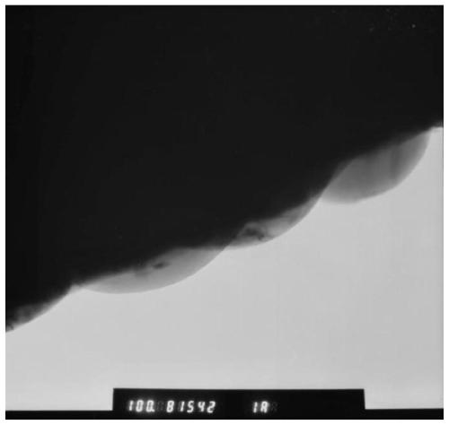
[0060] TEM observation was carried out on the above-mentioned coated and modified positive electrode material, and the results are shown in figure 1 , figure 1 TEM image of the coated modified cathode material prepared in Example 1. TEM characterization shows that a uniform coating layer can be observed on the surface of the material.

[0061] (4) Assemble lithium ion battery with the N...

Embodiment 2

[0066] (1) Weigh 0.16g LiClO 4 Add 0.008g initiator AIBN to 0.836g isobornyl acrylate IBOA, stir magnetically for 20min to form a homogeneous solution;

[0067] (2) Add the above solution into a beaker containing 50 g of ethanol, and disperse it ultrasonically for 2 hours;

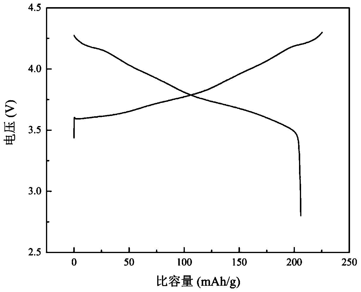
[0068] (3) Add 18g of NCM811 into the above ultrasonically dispersed solution, stir magnetically at 80°C for 24h, until the ethanol in the slurry is completely volatilized, and then heat-treat the slurry at 100°C for 3h to prepare the modified NCM811 material;

[0069] (4) Assemble a lithium-ion battery with the above-mentioned coated and modified NCM811 material, and test its electrochemical performance at room temperature (25°C) and a voltage range of 2.8 to 4.3V;

[0070] The test results show: the discharge capacity of the sample 0.1C of the comparative example is 204.0mAh / g, and the first Coulombic efficiency is 89.63%, while the discharge capacity of the sample 0.1C of Example 2 is 207.2mAh / g, and t...

Embodiment 3

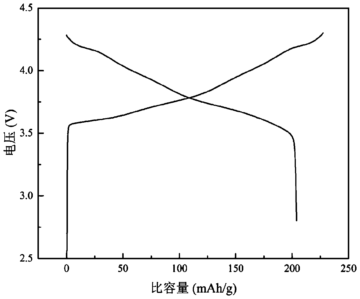
[0072] (1) Weigh 0.12g LiFSI and 0.006g photoinitiator 184 and add to 0.877g pentaerythritol tetraacrylate PETEA, stir magnetically for 30min to form a homogeneous solution;

[0073] (2) Add the above solution into a beaker containing 50 g of ethanol, and magnetically stir and disperse for 3 h;

[0074] (3) Add 20g of NCM811 into the above-mentioned ultrasonically dispersed solution, stir overnight magnetically, and irradiate the slurry with a UV lamp during stirring until the ethanol in the slurry is completely volatilized;

[0075] (4) Assemble a lithium-ion battery with the above-mentioned coated and modified NCM811 material, and test its electrochemical performance at room temperature (25°C) and a voltage range of 2.8 to 4.3V;

[0076] The test results show: the discharge capacity of the sample 0.1C of the comparative example is 204.0mAh / g, and the first coulombic efficiency is 89.63%, while the discharge capacity of the 0.1C sample of Example 3 is 205.4mAh / g, and the firs...


PUM

PropertyMeasurementUnit
Discharge capacityaaaaaaaaaa
Li-ion conductivityaaaaaaaaaa

Abstract

The invention provides a coating method for improving the ionic conductivity of a positive electrode material of a lithium ion battery. According to the invention, the method comprises the steps of adopting an in-situ solidification technology, dissolving lithium salt and an initiator in an organic monomer solvent, uniformly dispersing the positive electrode material in the organic solution, and uniformly curing the organic solution on the surface of the positive electrode material in manners of ultraviolet polymerization, thermal polymerization, electron beam polymerization and the like, so that a compact protective layer is formed. As the lithium salt is dissolved in the organic solvent, lithium ions can be conducted, the coating method not only can inhibit the side reaction between thepositive electrode material and the electrolyte, but also can improve the lithium ion conductivity of a positive electrode material body, so that the rate capability of the lithium ion battery is improved. Meanwhile, the positive electrode material prepared by the coating method has higher lithium ion conductivity, so that the positive electrode material is expected to be applied to an all-solid-state battery.

Description

technical field [0001] The invention belongs to the technical field of lithium ion batteries, and in particular relates to a coating method for improving the ion conductivity of a positive electrode material of a lithium ion battery and a coated modified positive electrode material. Background technique [0002] Compared with traditional secondary batteries, lithium-ion batteries have the advantages of high capacity density, good cycle performance and safety performance, and environmental friendliness, and are widely used in portable electronic products, electric vehicles, and energy storage fields. The positive electrode material is an important part of the lithium-ion battery, because its energy density is lower than that of the negative electrode, so it is a limiting factor for the performance of the entire lithium-ion battery. At present, commercialized batteries use organic solvent composite lithium salt as the electrolyte. During the cycle, side reactions will occur in...

Claims


Application Information

Patent Timeline
IPC IPC(8): H01M4/62H01M4/505H01M4/525H01M10/04H01M10/0525
CPCH01M4/505H01M4/525H01M4/624H01M4/628H01M10/0427H01M10/0525H01M2004/021H01M2004/028Y02E60/10Y02P70/50
Inventor 薛龙龙刘波黄进鑫谷穗任超时冯奇
Owner SAIC MOTOR
Learn More