Laser and photoelectric arc compound welding welding torch

A hybrid welding and torch technology, applied in laser welding equipment, welding equipment, metal processing equipment, etc., can solve the problems of high manufacturing and installation accuracy requirements, expensive equipment, and low energy conversion efficiency.

Pending Publication Date: 2020-07-07
CHENGDU LASER HYBRID TECH CO LTD
View PDF3 Cites 2 Cited by
  • Summary
  • Abstract
  • Description
  • Claims
  • Application Information

AI Technical Summary

Problems solved by technology

[0011] (1) A very precise position of the weldment is required (within the focus range of the laser beam), and the weldment needs to use a relatively complex fixture to ensure that the laser beam hot spot is aligned with the final position of the weldment; for thickness greater than 19mm The workpiece is not suitable for laser welding on the production line
[0012] (2) For materials with high reflectivity and high thermal conductivity such as aluminum, copper and their alloys, the application of laser beam welding is limited
[0013] (3) The energy conversion efficiency is usually lower than 10%; the weld bead solidifies quickly, and it is easy to generate pores and embrittlement
[0014] (4) Equipment is expensive
The main defects of these technologies include: only part of the laser beam passes through the plasma arc for hybrid welding, and the energy utilization rate is low; the use of part of the laser beam to irradiate the electrode to excite the plasma inevitably aggravates the burning of the electrode; in addition , whether it is a conical hollow electrode or a combined electrode, there are problems such as low reliability, high requirements for manufacturing and installation accuracy, and difficult electrode replacement, which directly limit the popularization and application of the above technologies

Method used


Image

  • Laser and photoelectric arc compound welding welding torch

Examples


Embodiment Construction

[0041] The technical solutions in the embodiments of the present invention will be clearly and completely described below in conjunction with the accompanying drawings in the embodiments of the present invention. Obviously, the described embodiments are only a part of the embodiments of the present invention, rather than all the embodiments. Based on the embodiments of the present invention, all other embodiments obtained by those of ordinary skill in the art without creative work shall fall within the protection scope of the present invention.

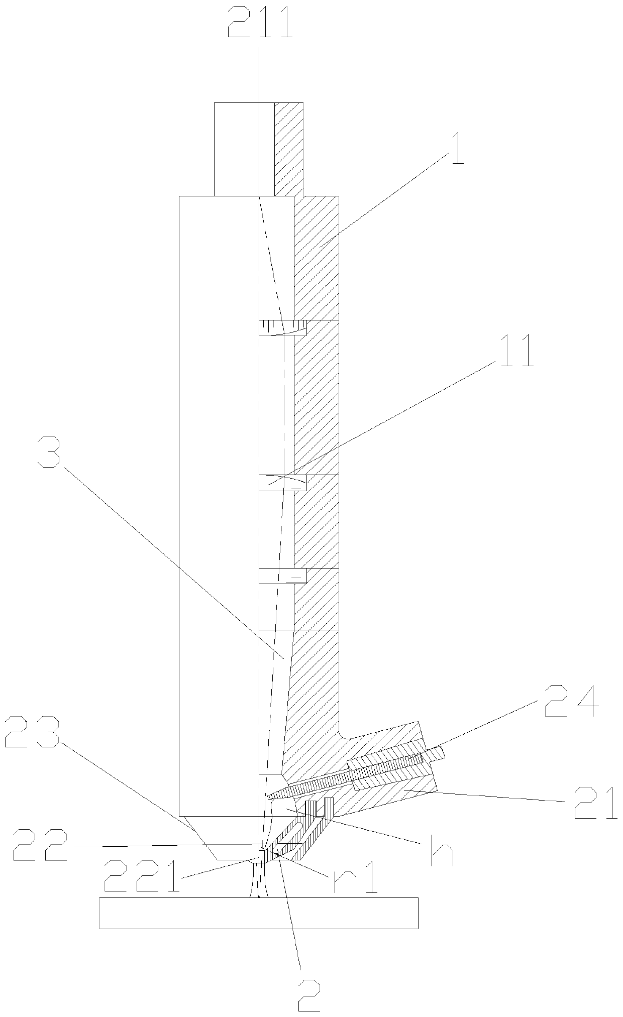
[0042] The present invention discloses a welding torch using laser beam and plasma arc for hybrid welding. The welding torch comprises a welding torch body with an input end 1, an output end 2 and a hollow cavity 3 located between the input end 1 and the output end 2. The laser beam is incident from the input end 1 and emitted from the output end 2. The torch body has a central axis 211, and the central axis 211 is the direction in which ...


PUM

PropertyMeasurementUnit
energy conversion efficiencyaaaaaaaaaa
reflectanceaaaaaaaaaa

Abstract

The invention provides a laser and photoelectric arc compound welding welding torch which comprises a welding torch body. The welding torch body is provided with an input end, an output end and a hollow inner cavity located between the input end and the output end. The welding torch body is provided with a center axis having a laser beam penetrating direction. The input end is provided with an incident ray lens used for focusing laser beams. The output end comprises an insulation lining, a compression nozzle, a protection nozzle and first non-melting electrodes. The insulation lining surroundsthe lower end of the hollow inner cavity. The compression nozzle is located at the output end of the insulation lining. The first non-melting electrodes are inlaid in the insulation lining and are arranged with the central axis with an oblique angle, the bottom ends of the first non-melting electrodes are located above a through hole of the compression nozzle, the distance between the bottom endsof the first non-melting electrodes and the upper surface of the through hole of the compression nozzle is h, and the distance between the bottom ends of the first non-melting electrodes is d; and the radius at of the laser beam passing through the position of the through hole of the compression nozzle is r1, and the radius of the through hole is larger than r1.

Description

Technical field [0001] The invention relates to a welding torch device for welding and coating metal materials, specifically, to a welding torch for laser and optical arc hybrid welding, and a laser and optical arc hybrid welding method adopting the invention. Background technique [0002] Welding is a processing and manufacturing technology that is crucial in various metal manufacturing industries and cannot be completely replaced so far. Welding operation refers to generating high energy density on the workpiece to form a molten pool and move the molten pool. Therefore, if the energy coupling efficiency between the welding tool and the workpiece can be improved, that is, the energy density incident on the workpiece, significant economic benefits can be obtained, depending on the material and welding technology used. [0003] One of them is plasma welding with high energy coupling density. Plasma welding is a process technology that uses plasma arc as an energy source to melt the...

Claims


Application Information

Patent Timeline
Patent Type & Authority Applications(China)
IPC IPC(8): B23K26/348
CPCB23K26/348
Inventor 王长春陈卓勤
Owner CHENGDU LASER HYBRID TECH CO LTD
Why Eureka
Try Eureka