Biocoatings and Implants

A bio-coating and implant technology, used in bone implants, coatings, tissue regeneration, etc., can solve the problems of poor long-term stability and limited bone ingrowth effect.

Active Publication Date: 2021-09-10
MICROPORT SINICA CO LTD
View PDF13 Cites 0 Cited by
  • Summary
  • Abstract
  • Description
  • Claims
  • Application Information

AI Technical Summary

Problems solved by technology

[0004] The purpose of the present invention is to provide a biological coating and implant to solve the problems of poor long-term stability and limited bone ingrowth effect of existing biological coatings and implants

Method used


Image

  • Biocoatings and Implants
  • Biocoatings and Implants
  • Biocoatings and Implants

Examples


Embodiment 1

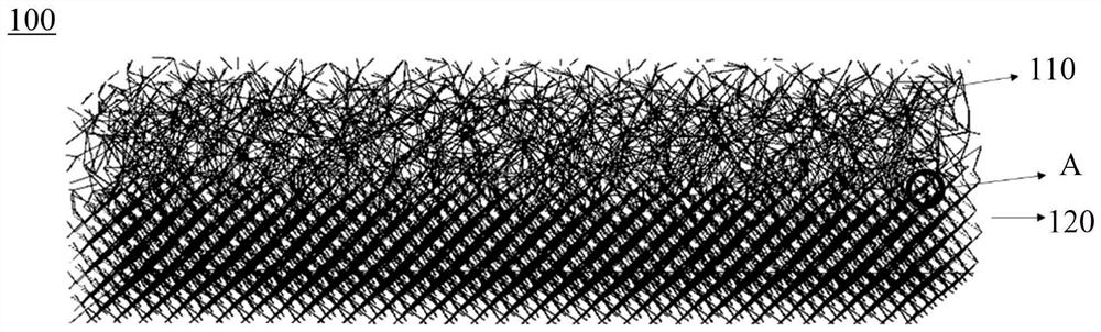
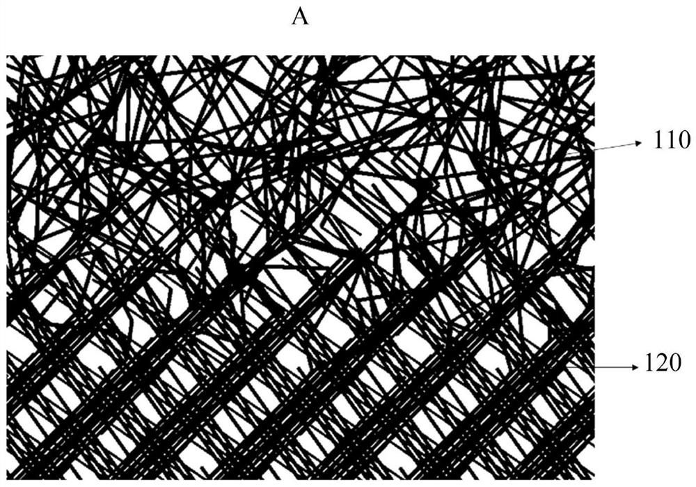
[0052] This embodiment provides a biological coating 100 . refer to figure 1 with figure 2 , figure 1 is a schematic structural view of the biological coating 100 in Embodiment 1 of the present invention, figure 2 yes figure 1 A partially enlarged schematic diagram of part A of the bio-coating 100 in , which includes a surface layer 110 and a middle layer 120 . The surface layer 110 is disposed on the middle layer 120 , the surface layer 110 is disposed on the outermost side of the biological coating 100 , and the porosity of the surface layer 110 is greater than that of the middle layer 120 .

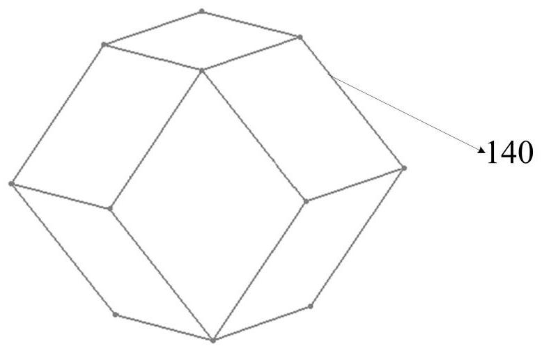
[0053] The surface layer 110 includes a plurality of first monomers connected in a disordered manner, and a plurality of first through holes are formed between the first monomers and inside the first monomers. refer to image 3 , image 3 It is a schematic structural diagram of a rhombic dodecahedron in Embodiment 1 of the present invention, and the first unit is a rhombic dod...

Embodiment 2

[0072] This embodiment provides a biological coating 100 . The difference between the biological coating 100 in this embodiment and the biological coating 100 in the first embodiment is that multiple second monomers in the intermediate layer 120 are connected in a disordered manner.

[0073] refer to Figure 8 with Figure 9 , Figure 8 is a schematic structural view of the biological coating 100 in Example 2 of the present invention, Figure 9 yes Figure 8Part B of the bio-coating layer 100 in FIG. The surface layer 110 is arranged on the middle layer 120, the surface layer 110 is arranged on the outermost side of the biological coating 100, the porosity of the surface layer 110 is greater than the porosity of the middle layer 120, so The intermediate layer 120 includes a plurality of second monomers connected in a disordered manner.

[0074] Due to the connectivity between the multiple first through holes in the biological coating 100, between the multiple second thro...

Embodiment 3

[0079] This embodiment provides a biological coating 100 . The difference between the biological coating 100 in this embodiment and the biological coating 100 in the first embodiment is that the second monomer is a diamond structure.

[0080] refer to Figure 11 with Figure 12 , Figure 11 is a schematic structural view of the biological coating 100 in Example 3 of the present invention, Figure 12 yes Figure 11 The partially enlarged schematic diagram of part C of the biological coating 100 in FIG. The surface layer 110 is arranged on the middle layer 120, the surface layer 110 is arranged on the outermost side of the biological coating 100, the porosity of the surface layer 110 is greater than the porosity of the middle layer 120, so The intermediate layer 120 includes a plurality of second monomers connected in a regular manner. The second unit is a diamond structure connected by a plurality of second connecting rods.

[0081] refer to Figure 13 , Figure 13 It ...


PUM

PropertyMeasurementUnit
pore sizeaaaaaaaaaa
thicknessaaaaaaaaaa

Abstract

The present invention provides a biological coating and implant. The biological coating includes a surface layer, the surface layer includes a plurality of first monomers connected in a disordered manner, and a plurality of first monomers are formed between the first monomers and inside the first monomers. A through hole. Since the surface layer is arranged on the outermost side of the biological coating, and the surface layer includes a plurality of first monomers connected in a disordered manner, the first monomers and the first monomers A plurality of first through holes are formed inside the body, that is, a plurality of first monomers in the surface layer are connected in a disordered manner, so the plurality of first through holes in the surface layer can be in a disordered state, so that Facilitate the growth of corresponding bone tissue cells into the superficial layer, thereby improving bone ingrowth and long-term stability.

Description

technical field [0001] The invention relates to the technical field of medical devices, in particular to a biological coating and an implant. Background technique [0002] Bio-coatings of traditional implants are often produced by titanium bead sintering, plasma spraying, corundum sandblasting and other processes. It is difficult for these processes to change the porosity of the bio-coating in a controllable manner, and it is difficult to ensure the connectivity between the pores, which is prone to stress shielding, and there are many layers of bio-coatings, between the bio-coating and the entity. Adhesive connection, poor connection stability, affects the effect of bone ingrowth and the mechanical properties of biological coatings and implants. In addition, these processes are relatively complex, with long production cycles and high costs. [0003] In the prior art, a porous metal bone tissue scaffold for 3D printing with gradient apertures is disclosed. The scaffold has ...

Claims


Application Information

Patent Timeline
Patent Type & Authority Patents(China)
IPC IPC(8): A61F2/82A61L27/56
CPCA61F2/82A61F2210/0076A61L27/34A61L27/56A61L2420/08A61F2002/30769B33Y80/00A61F2/28A61F2/30767A61F2002/3092A61F2002/3093A61F2002/30971A61F2002/30985A61F2/30907A61F2/30942A61L27/28A61L27/04B33Y10/00A61L2430/02
Inventor 辛晨卢凌霄常小龙刘翔乐承筠
Owner MICROPORT SINICA CO LTD
Why Eureka
Try Eureka