Shaking/rotating arc MIG gas shielded welding torch and method of use thereof

A technology of melting electrode gas and rotating arc, applied in the direction of arc welding equipment, electrode accessories, electrode support devices, etc., can solve the problems of narrow application range, complicated welding torch mechanism, high implementation cost, etc., and achieve the improvement of transmission positioning accuracy, welding The overall structure of the torch is compact and the effect of improving work reliability

Active Publication Date: 2021-07-13
JIANGSU UNIV OF SCI & TECH
View PDF10 Cites 0 Cited by
  • Summary
  • Abstract
  • Description
  • Claims
  • Application Information

AI Technical Summary

Problems solved by technology

The disadvantages of this type of welding torch are: ①The arc motion control method is single, the scope of application is narrow, and only a single rotating arc or shaking arc narrow gap welding can be realized; The positioning accuracy of the transmission is low, and the rotation resistance of the motor is large; ③A special sensing device for the arc rotation frequency or shaking frequency is used, and the device is installed between the motor mechanism and the brush mechanism, which makes the welding torch mechanism complicated; ④No The built-in cooling water circuit is set, and the torch body is easily heated by welding heat radiation; ⑤ no built-in gas circuit is provided, and only an external nozzle mechanism is used, which makes the torch nozzle mechanism complicated; ⑥ a conductive Rod and contact tip, poor process adaptability
Its disadvantages are: ①The rotary conductive seat is supported by double bearings, the arc rotary motion mechanism is complicated, and the positioning accuracy of the transmission is not high; ②The contact welding is fed through graphite powder, and its feeding stability is poor; ③The curved conductive tip It is a consumable part, and the implementation cost is high; ④A special position sensing mechanism is used to detect the swing angle of the contact tip, which makes the welding torch mechanism complicated; ⑤The structure of the conductive rod mechanism is fixed and single, and the adjustability and adjustability are not good. Good, poor process adaptability; ⑥ Only implemented for narrow gap arc welding

Method used


Image

  • Shaking/rotating arc MIG gas shielded welding torch and method of use thereof
  • Shaking/rotating arc MIG gas shielded welding torch and method of use thereof
  • Shaking/rotating arc MIG gas shielded welding torch and method of use thereof

Examples


Embodiment 3

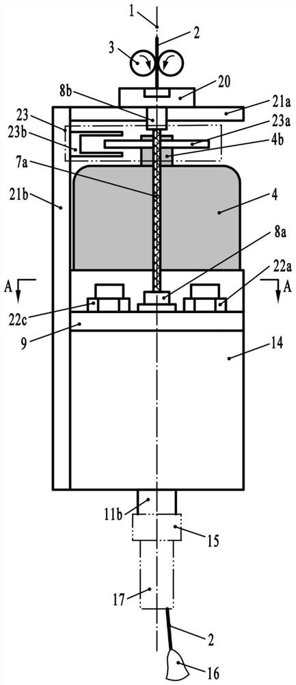
[0064] Welding torch embodiment 3: On the basis of welding torch embodiment 2, a hollow-shaft motor 4 with double-shaft extensions is used, and a shaft 4b protruding from the motor is provided for detecting arc shaking / rotation frequency and arc shaking The photoelectric switch device 23 of midpoint C, as shown in Fig. 2 (a) and Fig. 2 (b), its device is made of external grating disc 23a and optocoupler 23b, can also cover a dustproof cover (not drawn); The optical coupler 23b and the dust cover are fixedly connected to the support frame. At this time, the hollow shaft motor 4 is preferably a stepping motor or a DC motor.

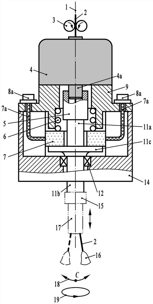
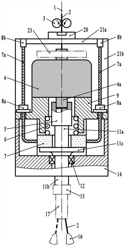
[0065] In the welding torch embodiment 1 and embodiment 2, the sensing device for detecting the arc shaking / rotation frequency and the arc shaking midpoint is not specially provided, or in the welding torch embodiment 3, the photoelectric switch device 23 is set at On the upper extension shaft 4b of the double shaft extension hollow shaft motor 4, the moto...

Embodiment 1

[0086] Embodiment 1 of the telescopic adjustment method of the conductive rod mechanism: a telescopic adjustment method of the conductive rod mechanism for shaking / rotating the arc melting electrode gas shielded torch, see Fig. 4(a), including the following steps:

[0087] ① Loosen the first lock nut 15a that is threadedly connected with the first retractable conductive rod or the first retractable conductive tip in the retractable conductive rod mechanism 17, so that the upper end surface of the first lock nut 15a Out of contact with the lower end surface of the arc movement output shaft 11d of the welding torch, it is in an unlocked state; ② Rotate the first retractable conductive rod or the first retractable conductive tip to make the first retractable conductive tip screwed in by threaded connection The upper end of the conductive rod or the first retractable conductive tip shrinks up or down in the central hole of the arc movement output shaft 11d; ③ reversely rotates the ...

Embodiment 2

[0089] Embodiment 2 of the telescopic adjustment method of the conductive rod mechanism: a telescopic adjustment method of the conductive rod mechanism for shaking / rotating the arc melting electrode gas-shielded torch, see Fig. 4(b) and Fig. 4(c), including the following steps :


PUM


Abstract

The invention discloses an oscillating / rotating arc melting pole gas-shielded welding torch and its use method, comprising the shaft extending from the bottom of the hollow shaft motor through a shaft coupling in the motor base and the shaft extending from the feeding plate passing through the brush mechanism Fixed connection, the extension shaft under the feeder plate passes through the support bearing installed in the brush holder and then connects with the eccentric or curved conductive rod mechanism; the motor holder and the brush holder are fixedly connected by connecting screws, and the connecting screws The inner hole and the built-in air circuit and cooling water circuit of the brush holder provide welding shielding gas and torch cooling; when there is no additional sensing device on the motor extension shaft, it can be identified / identified by pre-calibration or the built-in photoelectric encoder of the servo motor Detect arc shaking / rotation frequency and arc shaking midpoint; adjust the length of conductive rod mechanism through deployment or telescopic adjustment. The welding torch of the invention has the advantages of simple and compact structure, high transmission and positioning precision, good process adaptability and strong practicability, is suitable for shaking arc and rotating arc gas shielded welding, and can be extended for submerged arc welding.

Description

technical field [0001] The invention relates to the technical field of arc welding, in particular to a gas-shielded gas-shielded welding torch having shaking arc and rotating arc welding functions and a using method thereof. Background technique [0002] Gas metal arc welding is a kind of welding wire as the melting electrode, and uses argon, CO 2 Gas, or argon-rich mixed gas as a protective medium, or the arc welding method using self-shielded flux-cored wire, is suitable for welding in various positions such as flat positions and spatial positions, and is widely used in metal manufacturing. In order to improve the weld formation and improve the performance of the welded joint, it is often necessary to control the welding arc with swinging, rocking or rotating motion. [0003] Chinese patent application with publication number CN1657211A titled "Rotary arc narrow gap welding method and device driven by hollow shaft motor", and publication number CN101412143A titled "Shakin...

Claims


Application Information

Patent Timeline
Patent Type & Authority Patents(China)
IPC IPC(8): B23K9/28B23K9/26B23K9/173B23K9/095B23K9/32
CPCB23K9/28B23K9/26B23K9/173B23K9/32B23K9/095B23K9/0216B23K9/0213B23K9/295B23K9/122B23K9/125B23K9/186H02K11/22H02K5/203B23K9/164B23K9/285B23K9/287H02K5/145H02K7/003H02K9/19H02K9/28H02P6/16
Inventor 王加友王天威蒋达朱杰王彪庞建建张陆霄
Owner JIANGSU UNIV OF SCI & TECH
Why Eureka
Try Eureka