Feedback type multi-pole quantum cascade ring laser

A technology of ring lasers and quantum cascades, which is applied in the direction of lasers, phonon exciters, laser components, etc., to achieve the effect of enhancing stability

Active Publication Date: 2020-07-14
UNIV OF ELECTRONICS SCI & TECH OF CHINA
View PDF11 Cites 3 Cited by
  • Summary
  • Abstract
  • Description
  • Claims
  • Application Information

AI Technical Summary

Problems solved by technology

[0007] At present, for a wide range of applications in the mid-infrared and terahertz fields, there is a lack of a quantum cascade structure wi

Method used


Image

  • Feedback type multi-pole quantum cascade ring laser
  • Feedback type multi-pole quantum cascade ring laser
  • Feedback type multi-pole quantum cascade ring laser

Examples


Embodiment 1

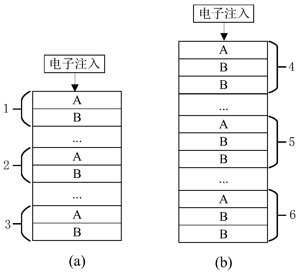
[0064] Such as figure 1 As shown, the schematic diagrams of two arrangement structures of the quantum cascade structure layer 9 in this embodiment, wherein, figure 1 The QCL stack units in (a) are all AB stacks, including the first QCL stack unit AB1, the i-th QCL stack unit AB2; the Nth QCL stack unit AB3, the quantum cascade structure layer 9 consists of N aforementioned QCL stacks Units are stacked to form an AB / … / AB / … / AB stack structure. figure 1 The QCL stack units in (b) are all ABB stacks, including the first QCL stack unit ABB4, the i-th QCL stack unit ABB5, and the N-th QCL stack unit ABB6. The quantum cascade structure layer 9 consists of N aforementioned QCL stacks Units are stacked to form an ABB / … / ABB / … / ABB stack structure.

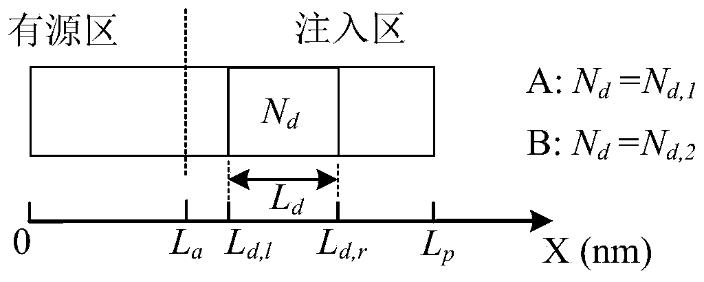
[0065] figure 1 (a), figure 1 Each QCL stack unit in (b) only contains two types of QCL subunits, A and B, and the two types of QCL subunits are composed of active regions and implanted regions, and the implanted regions only contain...

Embodiment 2

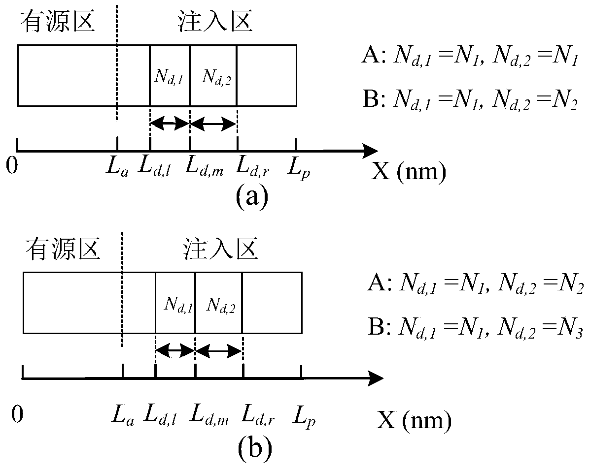
[0072] Such as image 3 As shown, in this embodiment, the QCL subunits of the quantum cascade structure layer 9 all have two doped regions. image 3 In (a), the doping concentration parameters of the two doped regions of the type A QCL subunit are the same, both being N 1 . The doping concentration parameters of the two doped regions of the B-type QCL subunit are N 1 and N 2 (N 1 ≠ N 2 ).

[0073] image 3 In (b), there are two sections of doping regions in the type A QCL subunit, and the doping concentration parameters of the two sections of doping regions are respectively N 1 and N 2 (N 1 ≠N 2 ). Type B QCL subunits have two sections of doping regions, and the doping concentration parameters of the two sections of doping regions are respectively N 1 and N 3 (N 3 ≠N 2 ).

[0074] same, image 3 Among them, the A and B QCL subunits are the same in other parameters except the doping concentration parameter, where other parameters include: the layer thickness se...

Embodiment 3

[0076] Such as Figure 5 As shown, it is a structural schematic diagram of the feedback multipole quantum cascade ring laser of the present invention. The feedback multipole quantum cascade ring laser is arranged sequentially from bottom to top along the z direction with a substrate 7, a collector 8, and a quantum level The structure layer 9, the quantum energy level matching layer 10, the base 11 and the emitter 12, the emitter 12 is etched into a strip straight waveguide 18 and a ring waveguide 19 structure. The base electrode 11 and the emitter electrode 12 are arranged in a ladder shape, and the collector electrode 8 and the quantum cascade structure layer 9 are also arranged in a ladder shape. Further, the collector electrode 8 may include a lower cladding layer, and the emitter electrode 12 may include an upper cladding layer. Specifically, the layer sequence of the device along the z direction from bottom to top is a heavy n-doped substrate 7, an n-doped collector 8, a ...


PUM


Abstract

The invention discloses a feedback type multi-pole quantum cascade ring laser. The laser comprises a substrate, a collector, a quantum cascade structure layer, a quantum energy level matching layer, abase and an emitter which are sequentially arranged from bottom to top, wherein stepped arrangement is formed between the emitter and the base and between the quantum cascade structure layer and thecollector; the laser further comprises a collector electrode arranged at the top of the collector electrode or below the substrate, a base electrode arranged at the top of the base electrode and an emitter electrode arranged at the top of the emitter electrode; an annular waveguide and a strip-shaped straight waveguide coupled with the annular waveguide are further etched on the laser, and the strip-shaped straight waveguide comprises a distributed feedback section and a coupling section. The laser is simple in design and good in tunability, can output multi-wavelength or wide-spectrum or chaotic laser or frequency comb, and can effectively reduce the application cost of mid-infrared and terahertz sources in wide mid-infrared and terahertz applications.

Description

technical field [0001] The invention belongs to the technical field of semiconductor lasers, in particular to a feedback multipole quantum cascade ring laser. Background technique [0002] Compared with the stimulated radiation transfer mechanism between the conduction band and the valence band of traditional quantum well lasers, quantum cascade lasers (Quantum Cascade Lasers, QCLs) have a unique cascade mechanism of transfer between subbands in the conduction band Instead, mid-infrared and terahertz band outputs can be generated directly. Compared with the existing mid-infrared and terahertz output generation methods, such as photoconductive mixing method, semiconductor built-in electric field method, optical rectification method, electro-optic sampling method, etc., the mid-infrared and terahertz output structure based on QCLs has conversion efficiency High, simple cavity structure, good on-chip integration, etc., are widely used in many civil and military applications in...

Claims


Application Information

Patent Timeline
IPC IPC(8): H01S5/042H01S5/10H01S5/34
CPCH01S5/0425H01S5/1071H01S5/3401
Inventor 王卓然袁国慧林志远张鹏年
Owner UNIV OF ELECTRONICS SCI & TECH OF CHINA
Why Eureka
Try Eureka