Thermal electron enhanced heat exchange device, heat exchange system and heat exchange method
A technology that enhances heat transfer and thermal electrons. It is applied in heat exchange equipment, indirect heat exchangers, lighting and heating equipment, etc. It can solve the problems that the cooling medium cannot effectively complete high heat flow heat transfer in a timely manner, and the local temperature of gas turbine blades is high. Achieve excellent heat conduction effect, improve heat exchange efficiency and optimize structure
- Summary
- Abstract
- Description
- Claims
- Application Information
AI Technical Summary
Problems solved by technology
Method used
Image
Examples
Embodiment approach 1
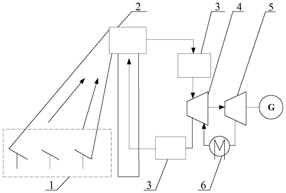
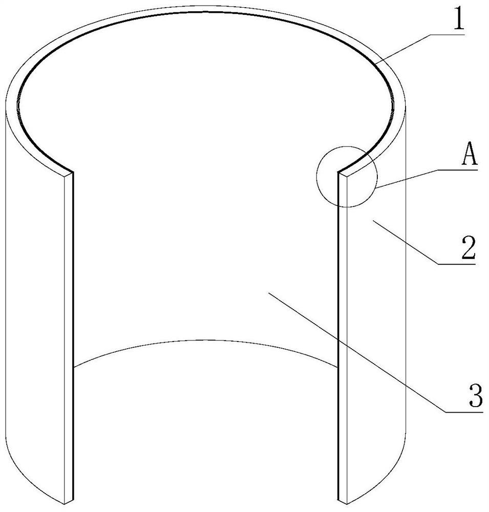
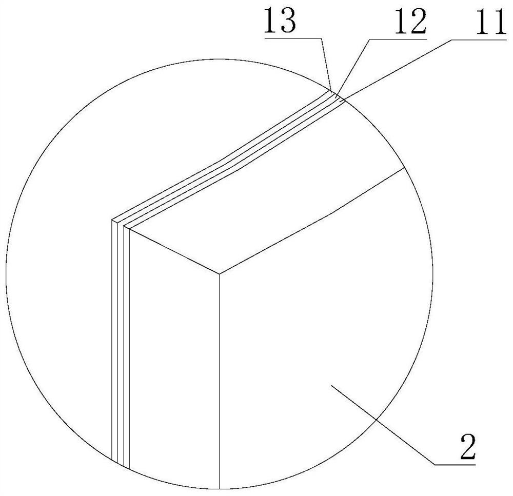
[0052] The first embodiment of the present invention provides a thermal electron enhanced heat exchange device, see figure 2 , image 3 and Figure 4 As shown, it includes a thermoelectric heat exchange layer 1 and a high-temperature heat source layer 2 , and the high-temperature heat source layer 2 is sheathed on the outside of the thermoelectric heat exchange layer 1 . Thermionic heat exchange layer 1 is divided into three layers, which are high temperature cathode layer 11, vacuum spacer layer 12 and low temperature anode layer 13 from outside to inside, and the inner space of low temperature anode layer 13 is formed as a low temperature medium channel 3 for the circulation of low temperature medium , the high-temperature cathode layer 11 can emit thermal electrons at high temperature, and the low-temperature anode layer 13 receives the thermal electrons, and the low-temperature medium exchanges heat with the low-temperature anode layer 13 in the low-temperature medium ch...
Embodiment approach 2
[0074] The second embodiment of the present invention provides a thermal electron enhanced heat exchange device. The second embodiment is a further improvement on the first embodiment. Parts not specifically described include reference numerals and text descriptions, which are the same as those of the first embodiment. The implementation is the same, and will not be repeated here.
[0075] The main improvement of the second embodiment over the first embodiment is that in the second embodiment of the present invention, the combination Figure 6 and Figure 7 From the point of view, the high-temperature heat source layer 2 is provided with a multi-layer thermoelectron heat exchange layer 1, the thermoelectron heat exchange layer 1 and the high-temperature heat source layer 2 are concentrically arranged, and the outer wall of the outermost thermoelectron heat exchange layer 1 is closely connected to the inner wall of the high-temperature heat source layer 2. Bonding, between two...
Embodiment approach 3
[0078] The third embodiment of the present invention provides a thermal electron enhanced heat exchange device. The third embodiment is a further improvement on the first to second embodiment. The second embodiment is the same, so it will not be repeated here.
[0079] The main improvement of the third embodiment compared with the first embodiment is that in the third embodiment of the present invention, considering high-temperature industrial projects such as nuclear power plant heat exchange and gas turbine blade heat exchange with a temperature exceeding 1000 ° C, the cathode material is made of resistant High temperature barium tungsten cathode, oxide cathode. to combine Figure 8 and Figure 9 It can be seen that the outer wall of the outermost thermionic heat exchange layer 1 is closely attached to the inner wall of the high-temperature heat source layer 2 , and the low-temperature medium channel 3 is between two adjacent thermionic heat exchange layers 1 .
[0080] In ...
PUM
| Property | Measurement | Unit |
|---|---|---|
| thickness | aaaaa | aaaaa |
Abstract
Description
Claims
Application Information
 - R&D
- Intellectual Property
- Life Sciences
- Materials
- Tech Scout
- Unparalleled Data Quality
- Higher Quality Content
- 60% Fewer Hallucinations
Browse by: Latest US Patents, China's latest patents, Technical Efficacy Thesaurus, Application Domain, Technology Topic, Popular Technical Reports.
© 2025 PatSnap. All rights reserved.Legal|Privacy policy|Modern Slavery Act Transparency Statement|Sitemap|About US| Contact US: help@patsnap.com


