Plastic panel vapor chamber and making method thereof

A manufacturing method and vapor chamber technology, applied in the field of heat exchange, can solve the problems of affecting vacuuming and filling, easy to be crushed, and high mold complexity, so as to reduce the number and cost of molds, reduce processing and manufacturing costs, and improve The effect of heat transfer efficiency

Pending Publication Date: 2020-08-18
BENSONG ENG PLASTICS HANGZHOU
View PDF2 Cites 0 Cited by
  • Summary
  • Abstract
  • Description
  • Claims
  • Application Information

AI Technical Summary

Problems solved by technology

At present, the existing vapor chamber structure is mostly manufactured by splicing and welding up and down, and the production process is complicated. In addition, this manufacturing method requires special molds to process parts of fixed size, resulting in high manufacturing costs.
[0007] 2) It is difficult and costly to control the high-precision structure in the production process of the vapor chamber made of metal
[0008] 3) The high density of the metal material makes the vapor chamber heavy, which limits its application in special scenarios such as electronics, automobiles, LEDs, and aerospace cooling products
[0009] 4) The heat dissipation capacity is limited. At present, the heat source and the condensation area of ​​the vapor chamber are not actually in the same plane, which leads to the fact that the condensed and reflowed working fluid actually flows back to the opposite area of ​​the heat source, which will cause the overall temperature of the vapor chamber to decrease. Reduced heat transfer efficiency
[0010] 5) When vapor chambers made of metal materials are sealed and connected to the metal working fluid filling interface by

Method used


Image

  • Plastic panel vapor chamber and making method thereof
  • Plastic panel vapor chamber and making method thereof
  • Plastic panel vapor chamber and making method thereof

Examples


Embodiment 1

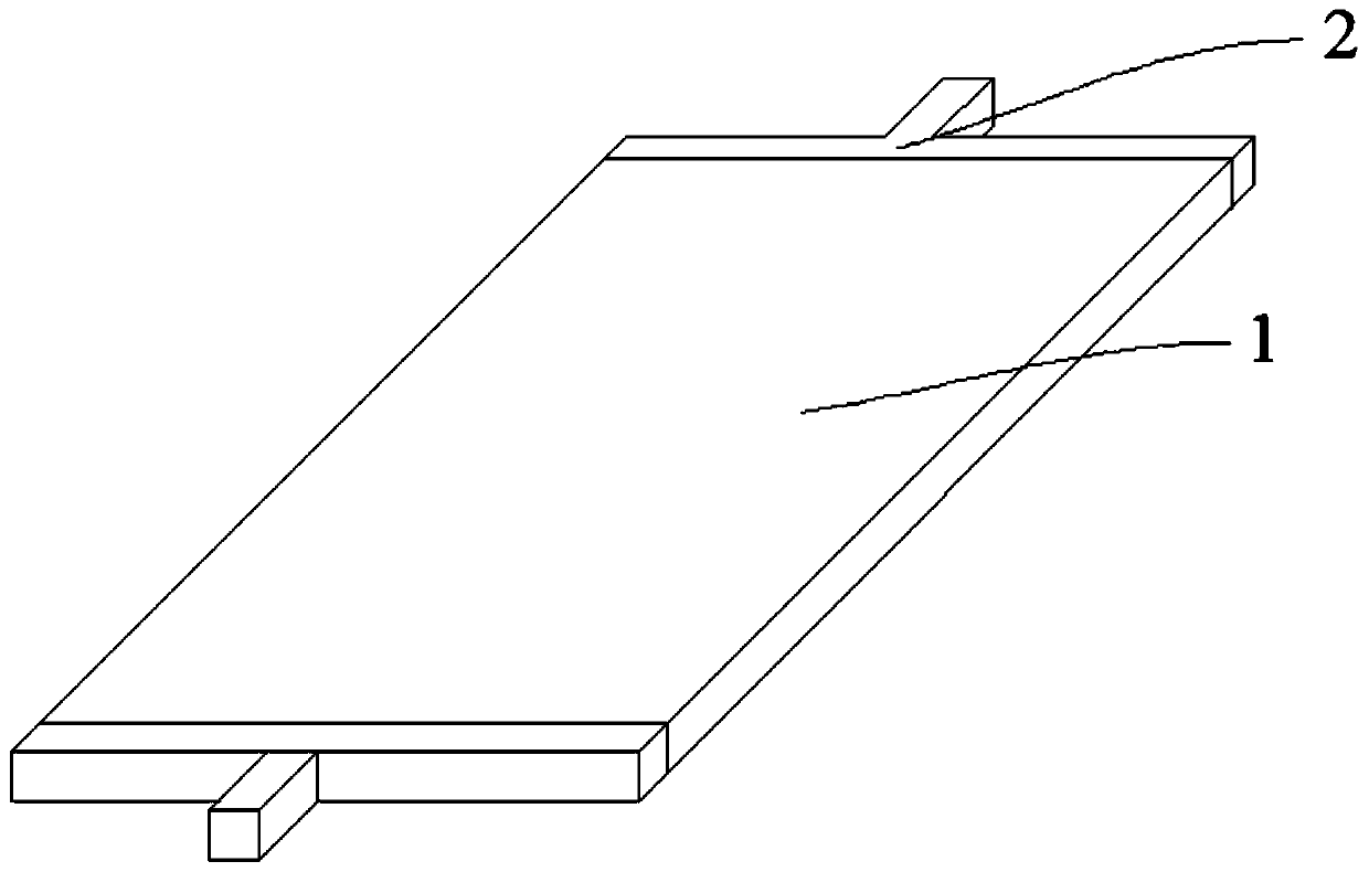
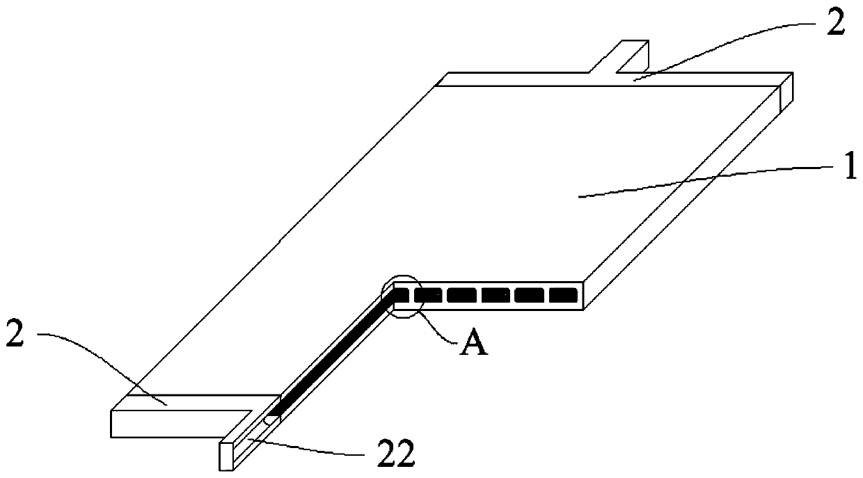
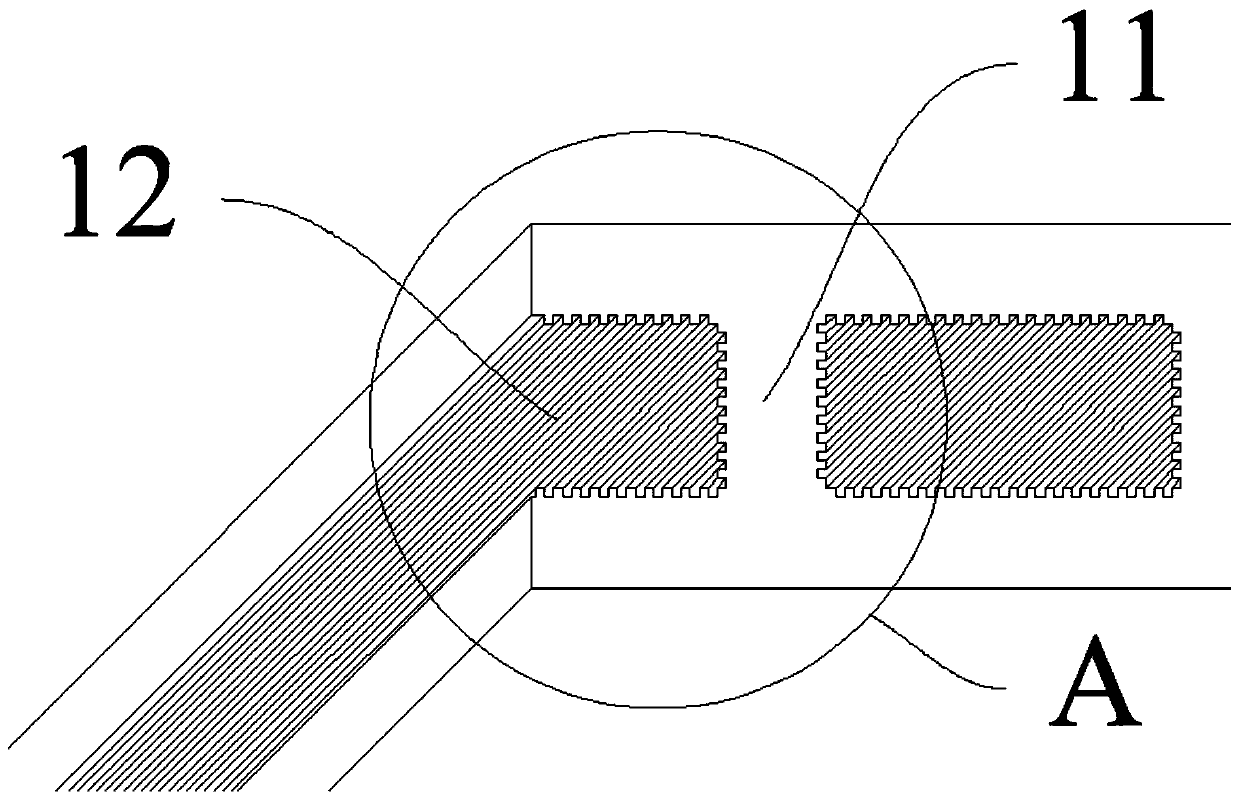
[0052] Such as Figure 1 ~ Figure 4 The shown one plastic flat vapor chamber includes: a cavity 1 and an encapsulation part 2, the cavity 1 cooperates with two encapsulation parts 2 at both ends to seal the cavity 1, and the inside of the cavity 1 is evacuated and filled with The cavity 1 is provided with a support structure 11, the cavity 1 is divided into several heat dissipation channels through the support structure 11, the surface of the heat dissipation channel in the cavity 1 is provided with a capillary structure 12, and the communication cavity 21 divides several heat dissipation channels. The channels communicate with each other, so that the working fluid can transfer heat to all parts of the entire vapor chamber faster, improving the heat transfer efficiency.

[0053] The capillary structure 12 on the surface of the support structure 11 is a microgroove parallel to the direction of the heat dissipation channel; the working fluid is acetone, which can absorb heat and...

Embodiment 2

[0068] Such as Figure 5 A flat plastic soaking plate shown has the same structure as that of Embodiment 1, the difference is that the outer surface of the cavity 1 is provided with a plurality of heat dissipation fins 3, and the material of the heat dissipation fins 3 is the same as that of the cavity heat-conducting plastic, a plurality of cooling fins 3 are arranged along the longitudinal direction of the cavity (that is, in the same direction as the cooling channel in the cavity 1), and the cooling fins 3 are parallel to each other, and the plurality of cooling fins 3 and the cavity 1 Integrated extrusion molding. It can reduce the processing procedure of the flat vapor chamber, greatly improve the production efficiency, reduce the cost and improve the heat dissipation performance. In addition, in this embodiment, the vacuumizing and filling steps of the working fluid can be as follows: connect the working medium filling equipment and the vacuuming equipment to the two en...


PUM

PropertyMeasurementUnit
Thermal conductivityaaaaaaaaaa
Surface tensionaaaaaaaaaa

Abstract

The invention belongs to the technical field of heat exchange, and particularly discloses a plastic panel vapor chamber. The plastic panel vapor chamber comprises a chamber body and a packaging part.The chamber body and the packaging part are used in cooperation to seal the chamber body. The chamber body is vacuumed and is filled with working media. Capillary structures are arranged on an inner surface of the chamber body. The working media can carry out heat absorption and heat transmission through phase changes. The chamber body is made of heat-conductive plastic with the heat conductivitycoefficient of 3W/(m.K) to 50 W/(m.K). Compared with the prior art, according to the plastic panel vapor chamber, because the chamber body is made of the heat-conductive plastic with the heat conductivity coefficient of 3W/(m.K) to 50 W/(m.K), the plastic panel vapor chamber has the advantages of being light in weight, simple in manufacturing technology, low in manufacturing cost and controllablein manufacturing accuracy; because the chamber body can be formed by adopting extrusion, and the packaging part is formed in an injection molding manner, the production efficiency can be greatly improved; because when production of various sizes of vapor chambers needs to be carried out, it is only needed that simple cutting treatment is carried out later, compared with a production technology with a metal material, the number of molds is greatly lowered, the cost is greatly reduced, and overall, obvious effects are achieved on energy saving and production cost reduction.

Description

technical field [0001] The invention belongs to the technical field of heat exchange, and in particular relates to a soaking plate and a manufacturing method thereof. Background technique [0002] With the development of information technology, the size of semiconductor components is getting smaller and smaller, while the power is getting bigger and bigger. At the same time, the calorific value is getting higher and higher, and the heat flux density per unit area is getting higher and higher. In order to make the components work well under the allowable temperature, various types of heat sinks are combined on the electronic components for heat dissipation. In the field of lighting, high-power light-emitting diodes (LEDs) have the advantages of higher efficiency, energy saving and longevity than traditional incandescent lamps and fluorescent lamps, so they are more and more widely used. However, the luminous efficiency of the light-emitting components of LED lamps is only 15...

Claims


Application Information

Patent Timeline
IPC IPC(8): F28D15/04F28F3/04F28F21/06
CPCF28D15/04F28F3/04F28F21/065
Inventor 沈博巩玉钊金彗星王一博张光辉
Owner BENSONG ENG PLASTICS HANGZHOU
Why Eureka
Try Eureka