Photo-thermal micro-flow mixer based on porous optical fibers

A technology of porous optical fiber and mixer, applied in the field of optofluidics, which can solve the problems of cumbersome preparation methods, complex technology and size requirements, and high cost

Active Publication Date: 2020-09-04
GUILIN UNIV OF ELECTRONIC TECH
View PDF16 Cites 0 Cited by
  • Summary
  • Abstract
  • Description
  • Claims
  • Application Information

AI Technical Summary

Problems solved by technology

[0008] Regardless of whether the above-mentioned microfluidic mixers are based on active or passive or photothermal effec...

Method used


Image

  • Photo-thermal micro-flow mixer based on porous optical fibers
  • Photo-thermal micro-flow mixer based on porous optical fibers
  • Photo-thermal micro-flow mixer based on porous optical fibers

Examples


Embodiment Construction

[0042] The present invention will be further described below in conjunction with the accompanying drawings and specific embodiments.

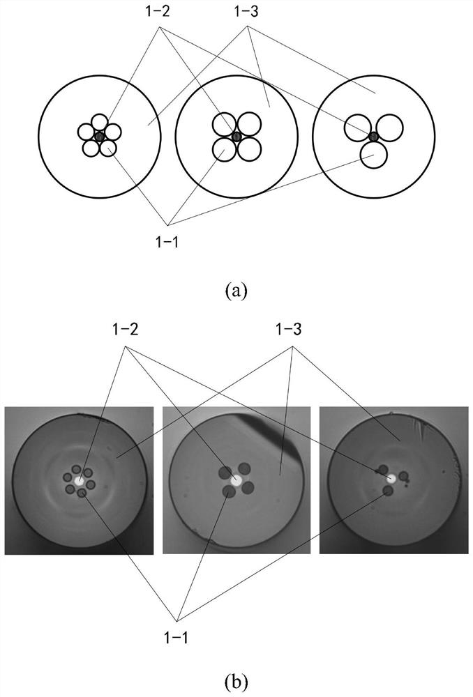
[0043] figure 1 A cross-sectional view of a holey fiber is shown, the holey fiber is composed of an air hole 1-1 that can be used as an inlet for entering a microfluidic liquid, a core 1-2 and a cladding 1-3 structure with a refractive index slightly higher than that of the cladding material consist of.

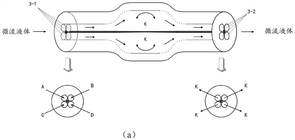
[0044] image 3 It shows the structure of the photothermal microfluidic mixer prepared by processing the holey fiber. The holey fiber is processed by the method of air pressure and heat fusion heating to prepare a section of mixing chamber, and the cladding expansion between the air holes in the mixing chamber changes. Thin until the complete thermal melt disappears, the fiber core runs through the entire heating chamber and is suspended in the middle, and after various liquids enter the mixing chamber at the same time, the molecules are acc...


PUM


Abstract

The invention provides a photo-thermal micro-flow mixer based on porous optical fibers. The photo-thermal micro-flow mixer is characterized by consisting of a section of porous optical fiber subjectedto micromachining treatment and a light source. The method comprises the following steps: a section of mixing chamber is prepared by processing a porous optical fiber through an air pressurization and hot melting heating method; the cladding between the air holes of the mixing chamber is expanded and thinned until complete hot melting disappears, the fiber core penetrates through the whole heating chamber and is suspended in the middle, and after various liquids enter the mixing chamber at the same time, molecules move in an accelerated manner due to heat radiation of the optical fiber core suspended in the mixing chamber to micro-flow liquids, so that the purpose of mixing is achieved. The porous optical fiber photo-thermal microfluidic mixer capable of being used for the microfluidic chip is simple to prepare, good in consistency, convenient to use in cooperation with the microfluidic chip, convenient and rapid to connect with a light source and suitable for large-scale mass production.

Description

[0001] (1) Technical field [0002] The invention relates to a photothermal microfluidic mixer based on a porous optical fiber, which is convenient for use with a microfluidic chip, and can also replace a microfluidic channel structure unit with a mixing function in the chip in micron-scale operation of microfluidics, and belongs to optofluidic technology field. [0003] (2) Background technology [0004] Microfluidics (Microfluidics or Lab-on-a-chip) refers to a system that uses microchannels of tens of microns or hundreds of microns to process or manipulate tiny fluids. After decades of development, microfluidic technology has become an emerging interdisciplinary subject involving chemistry, fluid physics, optics, microelectronics, new materials, biology and biomedical engineering. Due to the small volume of the sample in the microfluidic chip, the detection optical path is short, the optical detector with high sensitivity, fast response time, and low power consumption and t...

Claims


Application Information

Patent Timeline
IPC IPC(8): B01F13/00G02B6/02
CPCG02B6/02295G02B6/02314B01F33/305
Inventor 苑婷婷杨世泰张晓彤苑立波
Owner GUILIN UNIV OF ELECTRONIC TECH
Why Eureka
Try Eureka