DC boost converter and its control method

A DC boost and converter technology, applied in the direction of converting DC power input to DC power output, control/regulation systems, instruments, etc. Excessive excitation current of frequency transformers, etc., to achieve the effect of increasing switching frequency, improving comprehensive adaptability, and achieving stable control

Active Publication Date: 2021-05-18
INST OF ELECTRICAL ENG CHINESE ACAD OF SCI
View PDF6 Cites 0 Cited by
  • Summary
  • Abstract
  • Description
  • Claims
  • Application Information

AI Technical Summary

Problems solved by technology

The traditional isolated full-bridge Boost converter has the advantages of high step-up ratio and wide input range, but it needs to be equipped with an active clamp circuit that requires high control timing to absorb the energy of the transformer leakage inductance. In high-power applications, The leakage inductance of the transformer and the parasitic inductance of the clamping circuit will increase the voltage stress of the switching tube in the circuit, and this topology has problems such as complicated start-up process
The double-inductor half-bridge isolated Boost converter uses two half-bridge boost converters interleaved in parallel, which reduces the current stress of the switch tube and reduces the input current ripple, but it works in a hard switching state, and the voltage stress of the main switch tube is relatively high. High, and large switching losses limit the efficiency of the converter, not suitable for high-power applications
The Boost push-pull forward converter combines the Boost push-pull structure with the forward topology, which has the advantages of fewer components, high core utilization and good voltage output characteristics. However, the voltage stress of the switch tube is 2 times that of the full-bridge circuit. times, it is not suitable for applications with high input voltage, and the problem of DC bias will cause excessive excitation current of high-frequency transformer or even damage the switch tube

Method used


Image

  • DC boost converter and its control method
  • DC boost converter and its control method
  • DC boost converter and its control method

Examples


Embodiment Construction

[0052] The application will be further described in detail below in conjunction with the accompanying drawings and embodiments. It should be understood that the specific embodiments described here are only used to explain related inventions, not to limit the invention. It should also be noted that, for the convenience of description, only the parts related to the related invention are shown in the drawings.

[0053] It should be noted that, in the case of no conflict, the embodiments in the present application and the features in the embodiments can be combined with each other. The present application will be described in detail below with reference to the accompanying drawings and embodiments.

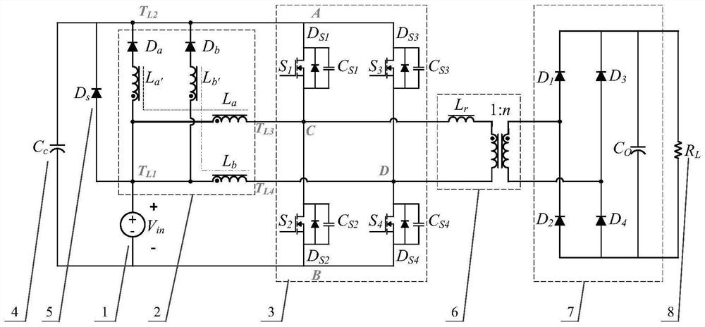
[0054] The invention provides a DC boost converter. Two boost circuits on the primary side of the converter work in parallel and complement each other to share power loss. The ripple frequency of the input and output current is twice the switching frequency of the main switching tube...


PUM


Abstract

The invention belongs to the technical field of DC converters, in particular relates to a DC boost converter and a control method thereof, and aims to solve the problems of large loss and narrow working range in traditional DC boost converters. The invention includes: an input power interface, a coupled inductance unit, a half-bridge unit, a bus support capacitor, a pre-charging diode, an isolation transformer, a rectification and filter circuit, and a power output interface. Among them, the input power interface can input a wide voltage range power supply such as photovoltaics or fuel cells; the coupled inductance unit includes A-phase coupled inductor and B-phase coupled inductor; the half-bridge unit includes the first bridge arm and the second bridge arm; the rectification and filter circuit includes Diode D 1 -D 4 , capacitance C o . In the present invention, the two boosting circuits on the primary side are connected in parallel to complement each other to share the power loss. The current ripple frequency is twice the switching frequency of the main switching tube. Not only can a transformer with a simple structure be used to provide a higher boosting ratio, but it can also be reduced by a resonant soft switch. Converter switching stress improves converter performance.

Description

technical field [0001] The invention belongs to the technical field of DC converters, and in particular relates to a DC boost converter and a control method thereof. Background technique [0002] Photovoltaic grid-connected power generation is one of the important ways to utilize solar energy. With the development of high-power power electronic semiconductor devices, the cost of DC transmission is gradually reduced, and flexible DC transmission technology has been developed rapidly. Due to the multi-terminal flexible DC system The characteristics of flexibility, reliability and economy are more suitable for distributed power generation and power market, and become an important utilization form of photovoltaic power generation in the future. [0003] Photovoltaic cells have the characteristics of soft output characteristics, low voltage levels, and large voltage fluctuation ranges. Therefore, they need to be boosted into stable DC high voltages after DC / DC power conversion wi...

Claims


Application Information

Patent Timeline
Patent Type & Authority Patents(China)
IPC IPC(8): H02M3/335
CPCH02M3/33569Y02B70/10Y02E10/56
Inventor 曹国恩王一波曹睿王哲王环
Owner INST OF ELECTRICAL ENG CHINESE ACAD OF SCI
Why Eureka
Try Eureka