
Laser shock assisted electric arc additive manufacturing method

An additive manufacturing and laser shock technology, applied in the field of additive manufacturing, can solve problems such as coarse grains, poor mechanical properties of components, and holes, and achieve the effects of inhibiting grain growth, improving performance, and accelerating bubble overflow.

Active Publication Date: 2020-09-25
BEIJING HANGXING MACHINERY MFG CO LTD
View PDF19 Cites 11 Cited by
  • Summary
  • Abstract
  • Description
  • Claims
  • Application Information

AI Technical Summary

Problems solved by technology

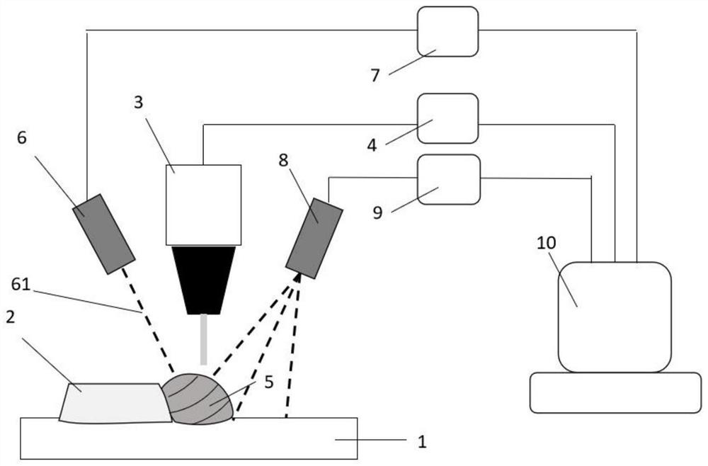
[0004] In view of the above analysis, the present invention aims to provide a laser shock assisted arc additive manufacturing method. During the arc additive process, the front of the liquid molten pool is cleaned synchronously by pulsed laser, and the rear is impacted and vibrated to solve the existing problems. In the technology, the internal grains of arc additive components are coarse, and there are defects such as holes and oxides, which lead to poor mechanical properties of components, so as to improve the performance of arc additive components

Method used


Image

  • Laser shock assisted electric arc additive manufacturing method
  • Laser shock assisted electric arc additive manufacturing method
  • Laser shock assisted electric arc additive manufacturing method

Examples


Embodiment 1

[0036] Such as Figure 1 to Figure 3 As shown, this embodiment provides a laser shock assisted arc additive manufacturing method, and the specific steps include:

[0037] Step 1: Establish a 3D model of the metal part to be processed, and design the arc additive processing path.

[0038] Specifically, according to the three-dimensional model of the metal part to be processed, the STL file of the three-dimensional model is obtained, and the STL file of the metal part is sliced ​​by the rapid prototyping system software, and then the surface contour of the metal part is output, and then the contour is meshed. Thus filling the outline. According to the obtained slice shape, design arc additive processing path, square section adopts linear scanning filling path, circular section adopts contour scanning filling path, complex section adopts multiple cross scanning methods to determine filling path, and finally obtains arc additive part processing path.

[0039] Step 2: Obtain the ...

Embodiment 2

[0060] In order to make it easier for those skilled in the art to understand the technical solution of the present invention more clearly, the laser shock assisted arc additive manufacturing method of the present invention will be specifically described below by taking the additive material of a 5A06 aluminum alloy cuboid boss member as an example.

[0061] The size of the parts to be processed is 50mm (length) * 50mm (width) * 30mm (height), and the welding wire is made of 5B06 aluminum alloy.

[0062] The specific processing steps are as follows:

[0063] Step 1: Establish a three-dimensional model of the 5A06 aluminum alloy cuboid component, obtain the STL file of the three-dimensional model, and perform single-layer slice processing on the STL file.

[0064] Step 2: Use CMT+P mode (pulse cold metal transition), obtain the required arc additive process parameters through process tests, and set the processing parameters. The welding wire adopts 5B06 aluminum alloy welding w...


PUM

PropertyMeasurementUnit
diameteraaaaaaaaaa
diameteraaaaaaaaaa
diameteraaaaaaaaaa

Abstract

The invention relates to a laser shock assisted electric arc additive manufacturing method, belongs to the field of additive manufacturing, and solves the problems that in the prior art, grains in anelectric arc additive component are thick and large, and holes, oxides and other defects exist. The laser shock assisted electric arc additive manufacturing method comprises the following steps that 1, an electric arc additive machining path is designed; 2, electric arc additive machining parameters are set; 3, the included angle between a laser cleaning head and a welding gun and machining parameters of a pulse laser cleaning machine are determined; 4, the included angle between a laser shock wave emitting head and the welding gun and machining parameters of a pulse laser shock emitter are determined; 5, the welding gun, the laser shock wave emitting head and the laser cleaning head work synchronously; and 6, an electric arc additive part is obtained according to the additive path. According to the laser shock assisted electric arc additive manufacturing method, through cooperative work of an electric arc additive device, a laser cleaning device and a laser impact device, the problemsthat the grains in the electric arc additive component are thick and large, and the holes, the oxides and the other defects exist are solved.

Description

technical field [0001] The invention relates to the field of additive manufacturing, in particular to a laser shock assisted arc additive manufacturing method, which is suitable for the wire arc additive manufacturing (Wire Arc Additive Manufacturing, WAAM) process. Background technique [0002] Arc additive manufacturing technology refers to the use of electric arc as a heat source to melt the metal wire, and then accumulate layers on the substrate according to the set forming path, and layer by layer until the metal parts are formed. The formed part is composed of full weld metal, which has high density, good metallurgical bonding performance, uniform chemical composition and good mechanical properties. Compared with laser and electron beam additive manufacturing technology, arc additive manufacturing technology has low cost and high forming speed. It has the advantages of being fast and capable of forming components with large dimensions and complex structures. [0003] ...

Claims


Application Information

Patent Timeline
Patent Type & Authority Applications(China)
IPC IPC(8): B23K26/348B23K26/342B23K26/70
CPCB23K26/348B23K26/342B23K26/702
Inventor 李建伟何智王志敏殷凤良张铁军刘玉平郭晓琳周小京陈宏伟
Owner BEIJING HANGXING MACHINERY MFG CO LTD
Learn More