Black water treatment equipment

A technology for processing equipment and black water, which is applied in the field of water treatment, can solve the problems of short-term operation, many connecting valves, complicated operation, etc., and achieve the effect of saving equipment and pipeline investment, and saving connecting pipelines and valves

Pending Publication Date: 2020-10-09
CHANGZHENG ENG
View PDF2 Cites 2 Cited by
  • Summary
  • Abstract
  • Description
  • Claims
  • Application Information

AI Technical Summary

Problems solved by technology

[0008] (1) At present, when the high-temperature and high-pressure solid-containing black water enters the flash tank through the pressure reducing valve, the steam, liquid and solid three-phase vapor-liquid separation internal parts generated will cause serious cavitation, erosion and wear, and the equipment life is short and cannot reach long run
[0009] (2) At present, the separation of vapor, liquid and solid in the flash tank is insufficient, and a large amount of liquid and solid is brought downstream, which affects the normal operation of downstream equipment
[0010] (3) Unseparated ash and inorganic salts dissolved in liquid water precipitate and crystallize at the pipes on the shell side of the heat exchanger to form scaling, which leads to the failure of the heat exchanger
[0011] (4) At present, gas-liquid separation and heat recovery are carried out in different equipment, and the space of the equipment cannot be fully utilized. The size of the connection between the two equipment is limited, causing the fluid velocity at the inlet of the heat exchanger to be too fast, which seriously erodes the heat exchanger
[0012] (5) At present, the black water treatment system has a large number of equipment, a large area, many connecting valves, complex operation, and many failure points
[0013] (6) At present, the solid content in non-condensable gas is large, which seriously pollutes the environment

Method used


Image

  • Black water treatment equipment

Examples


Embodiment Construction

[0031] Embodiments of the invention are described in detail below, but the invention can be practiced in many different ways as defined and covered by the claims.

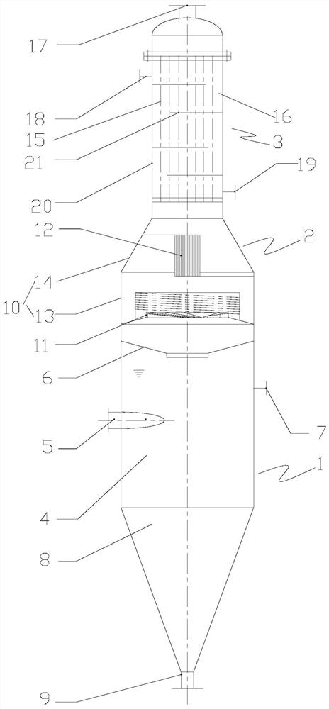
[0032] Please refer to figure 1 As shown, according to an embodiment of the present invention, the black water treatment equipment includes a lower flash section 1, a middle dust removal section 2 and an upper heat exchange section 3, the lower flash section 1 is used for flashing black water, and the middle dust removal section 2 It is connected to the top of the lower flash section 1 for gas-solid-liquid separation. The upper heat exchange section 3 is connected to the top of the middle dust removal section 2 for heat recovery. The lower flash section 1, the middle dust removal section 2 and the upper The heat exchange sections 3 communicate in sequence along the direction from bottom to top.

[0033] The black water treatment equipment in this scheme organically combines the flash tank and the heat exchanger, s...


PUM


Abstract

The invention provides black water treatment equipment. The black water treatment equipment comprises a lower flash evaporation section (1), a middle dust removal section (2) and an upper heat exchange section (3), wherein the lower flash evaporation section (1) is used for carrying out flash evaporation on black water; the middle dust removal section (2) is connected to the top of the lower flashevaporation section (1) and used for achieving gas-solid-liquid separation; the upper heat exchange section (3) is connected to the top of the middle dust removal section (2) and used for achieving heat recovery; and the lower flash evaporation section (1), the middle dust removal section (2) and the upper heat exchange section (3) are sequentially communicated in the direction from bottom to top. According to the black water treatment equipment disclosed by the invention, flash evaporation, dust removal and heat exchange can be realized in the same equipment, connecting pipelines and valvesare saved, and equipment and pipeline investment is effectively saved.

Description

technical field [0001] The invention relates to the technical field of water treatment, in particular to black water treatment equipment. Background technique [0002] Coal chemical industry, methanol, ether, dimethyl ether and other chemical and emerging energy companies form high-temperature and high-pressure solid-containing washing water at 220-280 °C during the cooling and washing process of coal gas and gasification gas, which is called gasification washing black water. Black water contains ammonia, carbon dioxide, hydrogen sulfide, carbon monoxide, hydrogen, nitrogen, argon, carbon oxysulfide and other gas components, as well as calcium carbonate, magnesium carbonate, sodium carbonate, calcium silicate, aluminum silicate, sodium silicate, etc. Inorganic salts. [0003] At present, the high-temperature and high-pressure solid-containing black water produced by the gasifier and scrubber is mostly treated by multi-stage flash evaporation and waste heat recovery, which i...

Claims


Application Information

Patent Timeline
Patent Type & Authority Applications(China)
IPC IPC(8): C02F1/06
CPCC02F1/06
Inventor 杨国政霍耿磊郑帅王守杰刘雪梅李伟彭书王正强
Owner CHANGZHENG ENG
Why Eureka
Try Eureka