Preparation method of periodic multi-directional thickness gradient thin films

A multi-directional and periodic technology, applied in ion implantation plating, metal material coating process, coating and other directions, can solve the problems that multi-directional thickness gradients cannot be realized, and achieve easy control of process conditions, simple operation, and wide The effect of applying the foreground

Inactive Publication Date: 2020-11-10
HANGZHOU DIANZI UNIV
View PDF6 Cites 0 Cited by
  • Summary
  • Abstract
  • Description
  • Claims
  • Application Information

AI Technical Summary

Problems solved by technology

At present, the method of preparing thickness gradient film is mainly to use mask plate shielding or oblique sputtering during sputtering, but the gradient film prepared by these methods has a thickness gradient change in a single direction on the film surface, and cannot achieve multi-directional thickness. Fabrication of Gradient and Periodic Thickness Gradient Arrays on the Same Thin Film

Method used


Image

  • Preparation method of periodic multi-directional thickness gradient thin films
  • Preparation method of periodic multi-directional thickness gradient thin films
  • Preparation method of periodic multi-directional thickness gradient thin films

Examples


Embodiment 1

[0054] Example 1 Preparation of periodic multi-directional thickness gradient iron film under grating mask

[0055] (1) Preparation of composite substrate: spin-coated a layer of PDMS (polydimethylsiloxane) with a thickness of 16 μm on the glass sheet;

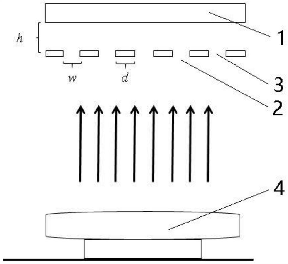
[0056] (2) Will be as figure 2 The grating mask shown is suspended and fixed above the composite substrate, and the mask specification is the size of the mesh w =63μm, rib width d=30μm, sputtering time 1min, the film thickness of the central area of ​​the mesh is t=6nm, and the mesh coverage area is t=4nm; adjust the distance between the mask and the composite substrate to h=120μm, put in the splash In the vacuum chamber of the radiometer, the iron target is fixed on the cathode, and the substrate is placed on the anode facing the target surface. After vacuuming, argon gas is introduced. The background pressure of the vacuum chamber is 2x10 -4 Pa, the argon pressure during sputtering is 0.5Pa, the sputtering voltage is: 260V; the s...

Embodiment 2

[0060] Example 2 Preparation of periodic multi-directional thickness gradient iron film under grating mask

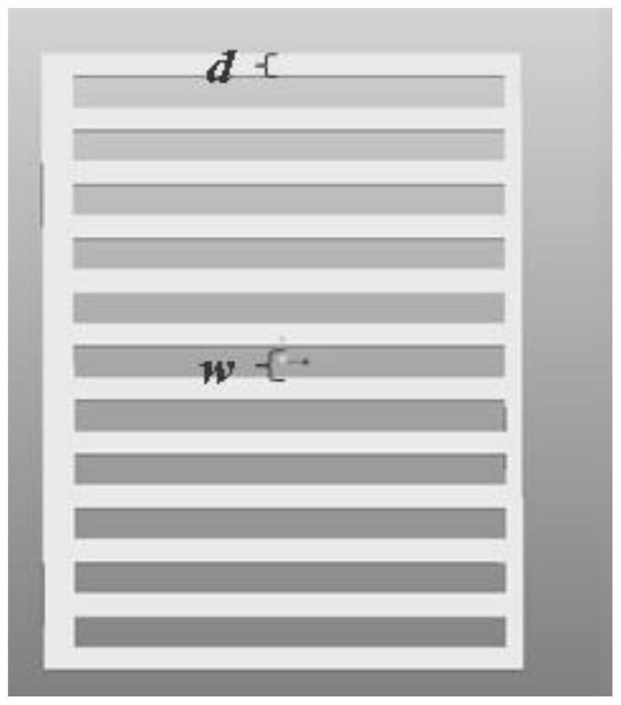
[0061] The difference between Example 2 and Example 1 is that the specifications and sputtering time of the grating mask are different: the size of the mesh w =127μm, rib width d=55μm, sputtering time 1min, film thickness in the center area of ​​the mesh is t=6nm, and other process conditions are exactly the same. The optical microscope image of the prepared periodic multi-directional thickness gradient iron film is as follows Image 6 As shown, the film thickness is 6 nm, and the mesh period is 127 μm.

Embodiment 3

[0062] Example 3 Preparation of periodic multi-directional thickness gradient iron film under grating mask

[0063] The difference between embodiment 3 and embodiment 1 is that the specifications and sputtering time of the grating mask are different: the size of the mesh w =260μm, rib width d =75μm, sputtering time 1min, the film thickness of the central area of ​​the mesh is t =6nm, the rest of the process conditions are exactly the same, the optical microscope image of the prepared periodic multi-directional thickness gradient iron film is as follows Figure 7 As shown, the film thickness is 6 nm, and the mesh period is 260 μm.


PUM

PropertyMeasurementUnit
thicknessaaaaaaaaaa
thicknessaaaaaaaaaa
thicknessaaaaaaaaaa

Abstract

The invention relates to the technical field of thin film materials, in particular to a preparation method of periodic multi-directional thickness gradient thin films. The method comprises the following steps that a mask plate is fixed above a substrate in a suspended mode, the mask plate is putted into a vacuum cavity of a sputtering instrument, a target material is fixed on a cathode, the substrate is putted on an anode opposite to a target surface, and after vacuumizing is carried out, inert gas is introduced, and the periodic multi-directional thickness gradient thin films are prepared through a sputtering method, wherein the distance between the mask plate and the substrate is h, the mask plate is provided with meshes, the mesh size is recorded as w, the rib width is recorded as d, h,w and d are adjustable, and h is greater than 0. According to the method, the multi-directional thickness gradient thin films can be prepared at a time and are periodically and densely arranged, theperiodic multi-directional thickness gradient thin films have the characteristic of high flux, the large-scale integration research and application are facilitated, and the application prospects in the field of flexible electronic materials and devices is wide.

Description

Technical field [0001] The invention relates to the technical field of thin film materials, in particular to a method for preparing periodic multi-directional thickness gradient thin films. Background technique [0002] With the rapid development of science and technology, in order to complete a certain use function, in addition to the demand for materials, the requirements for structural design are also getting higher and higher. Especially in today’s information age, the pace of life is accelerating. Whether in scientific research or commercial fields, in addition to requiring products to maintain high performance, they must also save costs, simplify production models, and make products thin and light. Easy to carry. Faced with these problems, the emergence of high-quality thin film structures has effectively solved these problems. Thin films have a long history of development, and the research on solid thin films first began in the 19th century. With the continuous developm...

Claims


Application Information

Patent Timeline
Patent Type & Authority Applications(China)
IPC IPC(8): C23C14/04C23C14/34C23C14/18
CPCC23C14/042C23C14/34C23C14/185
Inventor 余森江李会华卢晨曦李领伟
Owner HANGZHOU DIANZI UNIV
Why Eureka
Try Eureka