Ultra-wideband high-power amplifier

A high-power amplifier and ultra-wideband technology, which is applied in the direction of power amplifiers, amplifiers, amplifiers with semiconductor devices/discharge tubes, etc., can solve the problem of limited ultra-wideband high-power amplification capabilities, deterioration of broadband high-frequency efficiency, and optimal impedance Low-level problems, achieve good broadband power output capability and power gain capability, improve broadband power and high-frequency efficiency indicators, and improve stability and reliability

Active Publication Date: 2020-11-13
CHENGDU GANIDE TECH
View PDF11 Cites 2 Cited by
  • Summary
  • Abstract
  • Description
  • Claims
  • Application Information

AI Technical Summary

Problems solved by technology

[0004] (1) High-power and high-efficiency amplification capability is limited: the gate length of transistors in semiconductor processes is getting shorter and shorter, resulting in low breakdown voltage and high knee point voltage, which limits the power capacity of a single transistor
In order to obtain high power capability, multi-channel transistor power synthesis is often required, but the efficiency of the power amplifier is relatively low due to the energy loss of the multi-channel synthesis network, so the high power and high efficiency capabilities are poor
[0005] (2) Ultra-broadband high-power amplification capability is limited: in order to meet the high power index, multiple transistor power synthesis is required, but the load impedance of multi-channel synthesis is greatly reduced, resulting in a high impedance transformation ratio; in high impedance transformation ratio Realizing broadband characteristics is a great challenge
[0007] (1) In the traditional distributed power amplifier, the core amplification circuit is realized by a distributed amplification arrangement of multiple single field effect transistors. Due to the low power gain, low optimal impedance and isolation of single field effect transistors Poor and thus also lead to deterioration of reflective properties, thereby reducing synthesis efficiency;
[0008] (2) In order to simplify the analysis in the design of traditional distributed amplifiers, the influence of Miller capacitance on the circuit is often ignor

Method used


Image

  • Ultra-wideband high-power amplifier
  • Ultra-wideband high-power amplifier

Examples


Embodiment Construction

[0032] Exemplary embodiments of the present invention will now be described in detail with reference to the accompanying drawings. It should be understood that the implementations shown and described in the drawings are only exemplary, intended to explain the principle and spirit of the present invention, rather than limit the scope of the present invention.

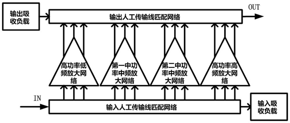
[0033] An embodiment of the present invention provides an ultra-wideband high power amplifier, such as figure 1 As shown, including input artificial transmission line matching network, input absorbing load, high power low frequency amplification network, first medium power intermediate frequency amplification network, second medium power intermediate frequency amplification network, high power high frequency amplification network, output artificial transmission line matching network and output absorb the load.

[0034] The input terminal of the input artificial transmission line matching network is the radio frequency i...


PUM


Abstract

The invention discloses an ultra-wideband high-power amplifier. The amplifier comprises an input artificial transmission line matching network, an input absorption load, a high-power low-frequency amplification network, a first medium-power medium-frequency amplification network, a second medium-power medium-frequency amplification network, a high-power high-frequency amplification network, an output artificial transmission line matching network and an output absorption load. According to the invention, the advantages of a single transistor structure amplifier and a distributed amplifier are combined, the ultra-wideband high-power amplifier has the advantages of being high in power output capacity, high in power gain, good in input and output matching characteristics, low in cost and the like under the ultra-wideband condition, meanwhile, the low breakdown voltage characteristic needing to face the integrated circuit technology in the design of the high-power power amplifier is avoided, and the stability and reliability of the circuit are improved.

Description

technical field [0001] The invention belongs to the technical field of field-effect transistor radio frequency power amplifiers and integrated circuits, and in particular relates to the design of an ultra-wideband high-power amplifier. Background technique [0002] With the rapid development of electronic warfare, software radio, ultra-wideband communication, wireless local area network and other military electronic countermeasures and communication, and civilian communication markets, RF front-end transceivers are also developing in the direction of high performance, high integration, and low power consumption. Therefore, the market urgently needs the radio frequency and microwave power amplifier of the transmitter to have ultra-wideband, high output power, high efficiency, low cost and other performances, and the integrated circuit is the key technology that is expected to meet the market demand. [0003] However, when using integrated circuit technology to design and impl...

Claims


Application Information

Patent Timeline
IPC IPC(8): H03F3/24H03F1/56H03F1/42H03F1/02
CPCH03F1/0205H03F1/42H03F1/565H03F3/245
Inventor 邬海峰王测天易永欣吕继平胡柳林童伟陈依军
Owner CHENGDU GANIDE TECH
Why Eureka
Try Eureka