An in-situ laser cleaning method for aircraft non-conductive composite coating

A technology of laser cleaning and composite coating, applied in the field of laser cleaning, can solve problems such as high labor intensity, low production efficiency, and damage to substrate materials, and achieve the effects of good electrical connection performance, high cleaning efficiency, and easy operation

Active Publication Date: 2021-07-13
WUHAN JINDUN LASER TECH CO LTD
View PDF0 Cites 0 Cited by
  • Summary
  • Abstract
  • Description
  • Claims
  • Application Information

AI Technical Summary

Problems solved by technology

One of the general problems of the grinding method is that it is impossible to precisely control the shape of the designated cleaning area. If the area is too small, it will affect the electrical bonding performance. If the area is too large, it will cause excessive damage to the surface treatment layer and reduce the corrosion protection performance.
The second problem is that it is impossible to precisely control the grinding depth. If the grinding is insufficient, the electrical conductivity cannot meet the low impedance requirement. If the grinding is excessive, the base material will be damaged and the structural strength of the aircraft will be reduced.
The third problem is that the secondary pollution caused by the grinding method will bring hidden dangers to the electrical bonding performance. Non-conductive secondary pollutants remain in the grooves produced by the sand particles, and the excessive speed of the mechanical grinding wheel will cause the base material to overheat and cause secondary oxidation.
The fourth problem is that the labor intensity is high and the production efficiency is low. There are more than 100 overlapping cleaning areas in an aircraft. It takes about 5-10 minutes for workers to clean up a small area, and about 30-60 minutes to clean up a large area.
In addition, there is often an assembly connection structure in the designated cleaning area, and it is required to ensure a complete surface treatment layer for the matching parts of the cleaning part, including electroplating layer, oxide layer, phosphating layer, etc. This connection structure often forms a restricted space. , the outstanding problem is that the grinding operation is difficult and difficult to implement, and it is easy to have insufficient grinding area and grinding depth at the parts where the mating parts are handed over, or accidentally damage the surface treatment layer of the non-essential cleaning area

Method used


Image

  • An in-situ laser cleaning method for aircraft non-conductive composite coating
  • An in-situ laser cleaning method for aircraft non-conductive composite coating
  • An in-situ laser cleaning method for aircraft non-conductive composite coating

Examples


Embodiment Construction

[0036] The principles and features of the present invention are described below in conjunction with the accompanying drawings, and the examples given are only used to explain the present invention, and are not intended to limit the scope of the present invention.

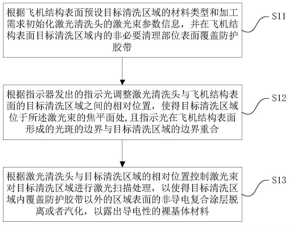
[0037] Such as figure 1 Shown, a kind of in-situ laser cleaning method of aircraft non-conductive composite coating, comprises the steps:

[0038] S11: Initialize the laser beam parameter information of the laser cleaning head according to the material type and processing requirements of the preset target cleaning area on the surface of the aircraft structure, and cover the surface of the non-essential cleaning parts in the target cleaning area with protective tape;

[0039] For example, the irradiation energy density of the laser beam is set so that the energy density of the laser beam is within the range of the damage threshold and the cleaning threshold of the substrate at the cleaning site, where the damage thre...


PUM

PropertyMeasurementUnit
wavelengthaaaaaaaaaa

Abstract

The invention relates to an in-situ laser cleaning method for non-conductive composite coatings of aircraft, which includes initializing laser beam parameter information of a laser cleaning head, and covering non-essential cleaning parts in a preset target cleaning area with protective tape; adjusting the laser cleaning head The position relative to the target cleaning part of the aircraft structure, so that the target cleaning area of ​​the aircraft structure is located at the focal plane of the laser beam, and the indicator light coincides with the target cleaning area; the laser beam is controlled to perform laser scanning processing on the target cleaning part of the aircraft structure, so that the aircraft structure The non-conductive composite coating on the surface of the target cleaning area other than the area covered by the protective tape is detached or vaporized to expose the conductive bare substrate material. The invention can avoid the damage of the surface treatment layer of the non-essential cleaning part in the target cleaning area by covering the protective tape, and realize the in-situ cleaning of the non-conductive composite coating on the surface of the designated area of ​​the aircraft, with high cleaning efficiency, accurate positioning and no non-conductive pollution No residue, good electrical connection performance, simple process, easy to operate, and environmentally friendly.

Description

technical field [0001] The invention relates to the technical field of laser cleaning, in particular to an in-situ laser cleaning method for aircraft non-conductive composite coatings. Background technique [0002] In the manufacturing process of aircraft parts, surface treatments such as oxidation, electroplating, and painting are required to ensure the corrosion protection performance of the aircraft and various functional requirements such as weather resistance, wear resistance, and lubrication. The corrosion protection process of the main body of the aircraft is metal oxide film and anti-corrosion coating. Metal oxide film is a non-conductive surface treatment layer, including chemical oxide film, sulfuric acid anodic oxidation film, chromic acid anodic oxidation film, etc. The paint layer is a kind of High-impedance organic dielectric coatings are generally divided into primers and topcoats. [0003] Aircraft assembly requires antenna lapping, current loop lapping, ant...

Claims


Application Information

Patent Timeline
Patent Type & Authority Patents(China)
IPC IPC(8): B08B7/00
CPCB08B7/0042
Inventor 金翔刘顿张骆任晋宇
Owner WUHAN JINDUN LASER TECH CO LTD
Why Eureka
Try Eureka