A method for recovering waste heat from exhaust gas
A technology of waste heat recovery and waste gas, which is applied in the field of waste heat recovery of waste gas, can solve the problem of low utilization rate of waste heat, achieve high added value and improve utilization rate
- Summary
- Abstract
- Description
- Claims
- Application Information
AI Technical Summary
Problems solved by technology
Method used
Image
Examples
Embodiment 1
[0032] A method for recovering waste heat from exhaust gas, comprising the steps of:
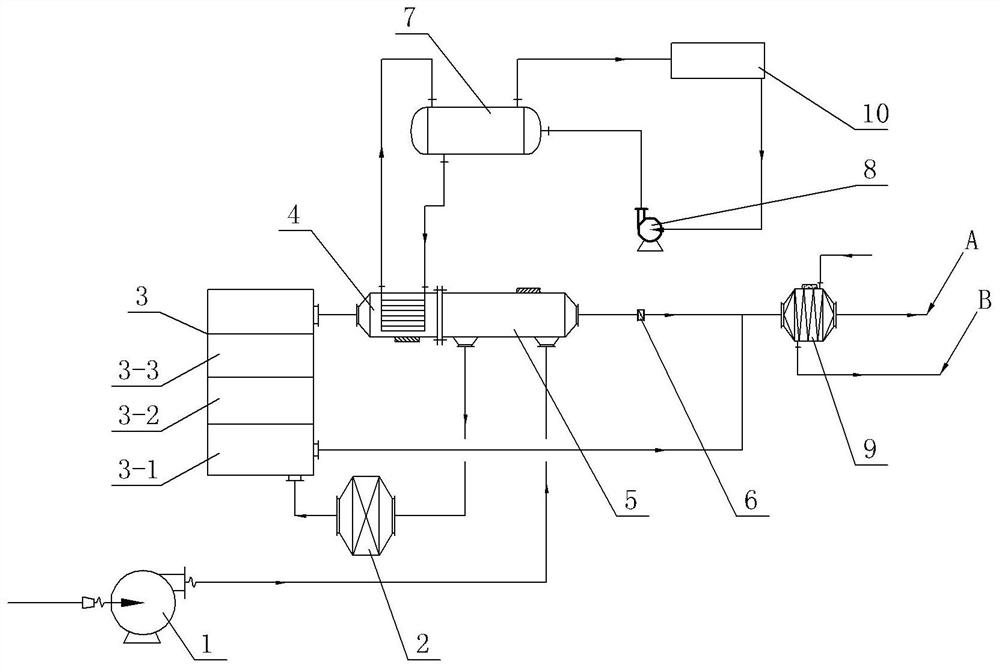
[0033] Step 1: Prepare as figure 1 The exhaust gas waste heat recovery system shown includes fan 1, flame arrester 2, catalytic oxidation bed 3, waste heat furnace 4, preheater 5, heat exchanger 9, steam drum 7, water pump 8 and pipelines. The preheater 5 includes a waste gas inlet, a waste gas outlet, a gas inlet and a gas outlet. The fan 1 communicates with the waste gas inlet of the preheater 5 through a pipeline, and the flame arrester 2 communicates with the waste gas outlet of the preheater 5 through a pipeline.
[0034] Catalytic oxidation bed 3 includes heat exchange section 3-1, heating section 3-2 and catalytic section 3-3, flame arrester 2, heat exchange section 3-1, heating section 3-2, catalytic section 3-3, waste heat furnace 4 , the gas inlet of the preheater 5 and the heat exchanger 9 are connected through pipelines in sequence, and a control valve 6 is installed on the pipe...
Embodiment 2
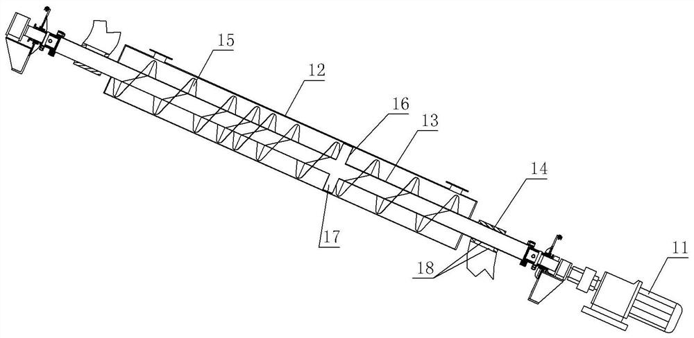
[0041] On the basis of Example 1, as figure 1 The shown heat exchange section 3-1 is provided with a heat exchange mechanism, such as figure 2 As shown, the heat exchange mechanism includes a servo motor 11, a hot gas pipe 12, a waste gas pipe 13 and two connecting pipes 14. The hot gas pipe 12 is obliquely fixed in the heat exchange section 3-1 by bolts, and the upper end of the hot gas pipe 12 passes through the internal channel. It communicates with the catalytic section 3-3, and the lower end of the hot gas pipe 12 communicates with the heat exchanger 9 through a pipeline.
[0042] The servo motor 11 is fixed and installed in the heat exchange section 3-1 by bolts. The model of the servo motor 11 can be selected as MR-J2S-100A. The side walls of the oxidation bed 3 are rotatably connected, and the waste gas pipe 13 is rotatably arranged in the hot gas pipe 12 .
[0043] The waste gas pipe 13 is welded with a helical piece 15 and a collection plate 16 , and the collectio...
Embodiment 3
[0051] On the basis of Example 2, such as figure 2 As shown, in this embodiment, the inclination angle of the hot gas pipe 12 is 30°, the collecting pan 16 is located at the lower end of the waste gas pipe 13, and the spiral pieces 15 at the upper and lower ends of the waste gas pipe 13 are more sparsely distributed, and the spiral pieces 15 in the middle of the waste gas pipe 13 The spacing distribution is denser. In addition if figure 1 As shown, the waste heat furnace 4 and the preheater 5 are integrated, that is, the tail of the waste heat furnace 4 and the gas inlet of the preheater 5 are directly welded and communicated.
PUM
 Abstract
Description
Claims
Application Information
 - R&D
- Intellectual Property
- Life Sciences
- Materials
- Tech Scout
- Unparalleled Data Quality
- Higher Quality Content
- 60% Fewer Hallucinations
Browse by: Latest US Patents, China's latest patents, Technical Efficacy Thesaurus, Application Domain, Technology Topic, Popular Technical Reports.
© 2025 PatSnap. All rights reserved.Legal|Privacy policy|Modern Slavery Act Transparency Statement|Sitemap|About US| Contact US: help@patsnap.com


