Device for evaporation by utilizing gas moisture content difference

A gas and steam technology, applied in evaporation, chemical instruments and methods, separation methods, etc., can solve the problems of increased heat transfer temperature difference loss, high cost, complex working principle of multi-effect evaporation, etc., and achieve the effect of less energy consumption

Pending Publication Date: 2020-12-08
安徽聚云环保设备制造有限责任公司
View PDF0 Cites 2 Cited by
  • Summary
  • Abstract
  • Description
  • Claims
  • Application Information

AI Technical Summary

Problems solved by technology

[0004] 1. Multi-effect or MVR evaporation equipment is too bulky, and there are many parts, disassembly and installation are more troublesome. The working principle of multi-effect evaporation is complicated, and the temperature in the tube needs to be observed at any time. Someone needs to be by the machine all the time, non-technical personnel It is more complicated to operate
[0005] 2. In multi-effect evaporation, as the number of effects increases, the temperature difference loss of heat transfer increases, which greatly reduces the production intensity of the evaporator and doubles the cost of equipment. If the number of effects is too large, a certain investment cost will be increased.
[0006] 3. The effective temperature difference of the MVR evaporator is small, the heat exchange area is large, the equipment cost is too high, and the evaporation capacity is small. If you want to increase the evaporation capacity from the original design, the output of the secondary steam will increase. The operating current of the compressor exceeds the standard, and the temperature drop will cause evaporation. volume reduction
After reducing the estimated evaporation, the secondary steam is not enough to meet the compressor inlet requirements, which will cause surge, reduce the steam volume, and be forced to stop
[0007] 4. The multi-effect or MVR evaporation equipment adopts the method of negative pressure evaporation. The main body of the equipment needs to be made of expensive metal, which is expensive and easily corroded at high temperature.

Method used


Image

  • Device for evaporation by utilizing gas moisture content difference

Examples


Embodiment

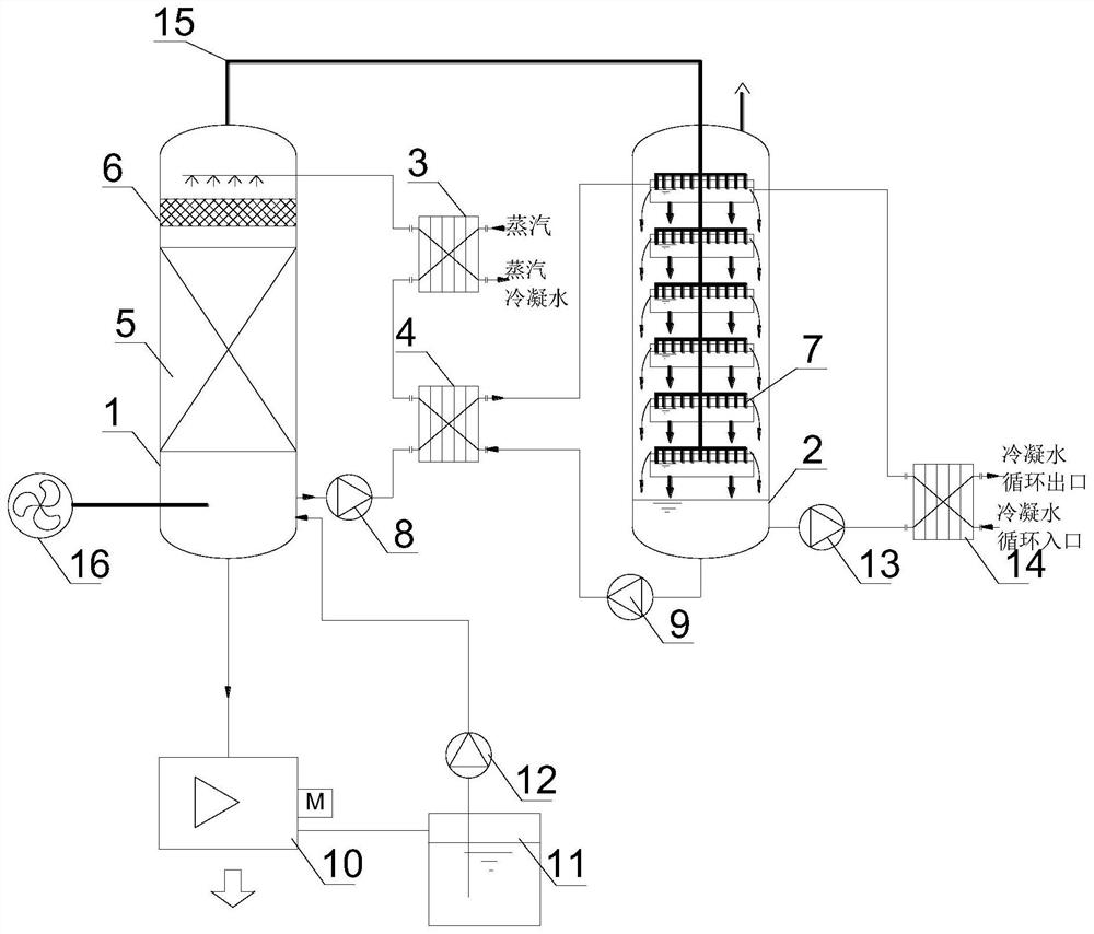
[0036] Please refer to figure 1 , specifically as figure 1 One embodiment of the invention is shown.

[0037] This embodiment provides a device for evaporating by using the difference in humidity of the gas, including a heating tower 1, a cooling tower 2, a centrifuge 10, a centrifuge mother liquor tank 11, and a centrifugal fan 16; the lower part of the heating tower 1 communicates with the centrifugal fan 16. Centrifugal blower 16 sends fresh air into heating tower 1, and the bottom of heating tower 1 communicates with centrifuge 10, and the other end of centrifuge 10 links to each other with centrifugal mother liquor tank 11, and centrifugal mother liquor tank 11 communicates with heating tower 1 bottom; It also includes a heat exchange assembly, the lower part of the temperature rise tower 1 is also communicated with the top of the temperature rise tower 1 through the heat exchange assembly, the temperature rise tower 1 is provided with a special filler 5, and the top of ...


PUM


Abstract

The invention provides a device for evaporation by utilizing gas moisture content difference, and relates to the technical field of chemical wastewater. The device comprises a heating tower, a coolingtower, a centrifugal machine, a centrifugal mother liquor tank and a centrifugal fan, the lower part of the heating tower is communicated with the centrifugal fan, the bottom of the heating tower iscommunicated with the centrifuge, the other end of the centrifuge is connected with the centrifugal mother liquor tank, and the centrifugal mother liquor tank is communicated with the lower part of the heating tower; the lower part of the heating tower is further communicated with the top of the heating tower through the heat exchange assembly, special filler is arranged in the heating tower, thetop of the heating tower is connected with a flow guide pipe, the other end of the flow guide pipe is communicated with the cooling tower and extends to the bottom in the cooling tower, a tower tray is arranged in the cooling tower, and the bottom of the cooling tower is further communicated with the heat exchange assembly; the device further comprises a water cooling circulation assembly which communicates with the cooling tower, and the top of the cooling tower is further connected with the heat exchange assembly. The device has the advantages of low energy consumption, simplicity and convenience in maintenance, high comprehensive utilization rate and low manufacturing cost.

Description

technical field [0001] The invention relates to the technical field of chemical wastewater, in particular to a device for evaporating by utilizing the moisture content difference of gas. Background technique [0002] With the rapid development of my country's economic construction, industrial enterprises continue to grow and develop, which has played a positive role in promoting the take-off of my country's national economy. However, in addition to development, a large amount of hazardous waste has also been produced, including heavy metal waste, waste emulsion, waste organic solvent, waste paint, waste paint, waste cyanide, waste medicine, etc. The components of these hazardous wastes are complex. If they are not handled properly, they will not only easily cause air, water and soil pollution, but also seriously affect the ecological environment and the health of the people. At present, the disposal methods of hazardous waste mainly include reduction treatment + disposal, o...

Claims


Application Information

Patent Timeline
Patent Type & Authority Applications(China)
IPC IPC(8): B01D1/00
CPCB01D1/00
Inventor 李万双陈浩孙权沈芸
Owner 安徽聚云环保设备制造有限责任公司
Why Eureka
Try Eureka