Column full-section partition plate type stirrup-free fiber reinforced concrete mixed frame joint

A technology of reinforced concrete columns and joints, which is applied in the field of joints of reinforced concrete column-steel beam hybrid frame structures, which can solve the problems of difficult plastic deformation in welding affected areas, narrow space for concrete pouring and vibration, and warping deformation of end plates out of plane To achieve the effect of improving the applicability and implementability, reducing the difficulty of concrete pouring, and preventing the column end from being damaged under pressure

Pending Publication Date: 2020-12-08
ZHEJIANG UNIV
View PDF0 Cites 2 Cited by
  • Summary
  • Abstract
  • Description
  • Claims
  • Application Information

AI Technical Summary

Problems solved by technology

[0003] 1. Existing beam-through joints ( Figure 5 ), due to the narrow steel beam flange, the lever reaction force causes the stress concentration of the concrete at the end of the column to cause pressure failure, and the energy dissipation capacity and ductility of the joint are poor, which needs to be avoided by complex structural measures during design; at the same time, due to the steel beam flange and The web runs through the joints, and the shear stirrups in the joint area must pass through the webs, which makes it difficult to configure the stirrups; and no matter whether the vertical pouring or horizontal pouring, there are dead corners in the concrete pouring space, it is difficult to ensure the quality of the pouring
[0004] 2. Nodes in the form of existing column penetrations ( Image 6 ), the flange of the steel beam is not connected, and stress concentration occurs at the end plate, and the end plate is prone to out-of-plane warping deformation, which makes it difficult to ensure the effective transfer of stress at the beam end from one side to the other; the weld between the steel beam and the end plate The requirements are high, and it is difficult to develop plastic deformation in the welding-

Method used


Image

  • Column full-section partition plate type stirrup-free fiber reinforced concrete mixed frame joint
  • Column full-section partition plate type stirrup-free fiber reinforced concrete mixed frame joint
  • Column full-section partition plate type stirrup-free fiber reinforced concrete mixed frame joint

Examples


Embodiment 1

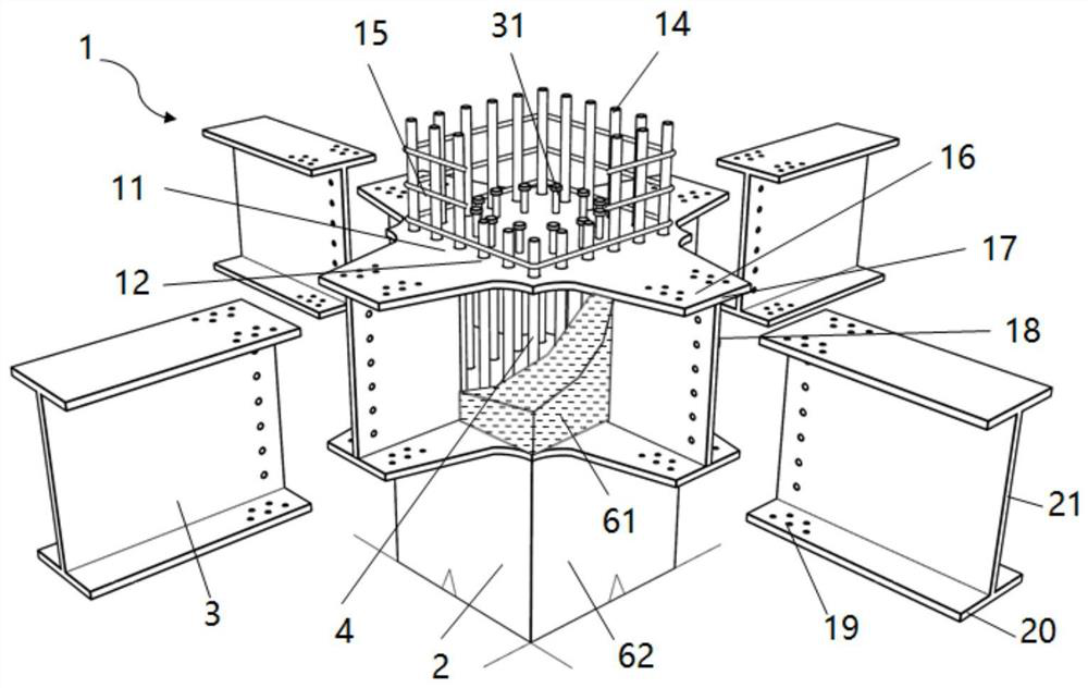
[0042] Such as figure 1 As shown, the hybrid frame node 4 of this embodiment is the node where the reinforced concrete column 2 and the steel beam 3 are connected to each other in the hybrid frame structure system 1;

[0043] The gusset plate 11 is composed of two upper and lower steel plates. In order to avoid local stress concentration to cause pressure damage at the end of the node column, at the same time ensure that the connection between the left and right steel beam flanges 20 has sufficient strength and rigidity, and at the same time facilitate the integrated prefabrication of the node 4 and the reinforced concrete column 2 , the horizontal gusset plate 11 in the form of a full-section partition of the column is adopted; in order to reduce the construction difficulty of the node 4 and ensure the accuracy of the reinforcement, the gusset plate 11 is provided with round holes 12 corresponding to the upper and lower sides, and the longitudinal steel bars 14 of the column ...

Embodiment 2

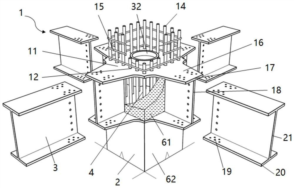
[0047] Such as figure 2 As shown, it is the same as in Example 1, the column is in the form of a full-section partition, no stirrups are provided in the core area of ​​the joint, and fiber reinforced concrete 61 is used.

[0048] The difference from Example 1 is that in order to prevent the concrete in the round hole 12 where the column longitudinal steel bar 14 is pierced from not being filled and compacted, resulting in relatively large relative sliding between the reinforced concrete column 2-horizontal gusset plate 11-concrete 61 in the node core area The displacement affects the seismic performance of the node 4, and the vertical circular steel pipe protrusions 32 are welded on the outer side or inner and outer sides of the upper and lower gusset plates 11 to form a horizontal shear key and effectively reduce the sliding deformation. The rest of the structure is similar to Example 1.

Embodiment 3

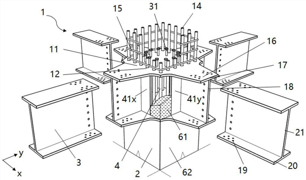
[0050] Such as image 3 As shown, it is the same as in Example 1, the column is in the form of a full-section diaphragm, no stirrups are set in the core area of ​​the joint, fiber reinforced concrete 61 is used, and vertical studs 31 shear keys are installed on the outer sides of the upper and lower joint plates.

[0051] The difference from Example 1 is that although the shear strength of fiber reinforced concrete 61 is higher than that of ordinary concrete, when the amount of fiber per unit volume exceeds a certain level, the shear strength of fiber reinforced concrete 61 will no longer increase. Therefore, when the shear force acting on the joint is large and the shear strength provided by the fiber-reinforced concrete 61 in the joint is insufficient, it is necessary to add steel to provide shear resistance. The purpose of the present invention is to omit the stirrups and simplify the construction process of the joints. Therefore, the addition of stirrups or the addition of...


PUM


Abstract

The invention relates to the field of concrete structures and combined structure buildings, and provides a reinforced concrete column-steel beam mixed frame joint adopting a column full-section partition plate type and fiber reinforced concrete. An upper horizontal joint plate and a lower horizontal joint plate which are in the column full-section partition plate type are adopted; round holes areformed in the peripheries of the joint plates, and column longitudinal steel bars penetrate through the round holes; horizontal shear keys are arranged on the surfaces of the joint plates; no stirrupis arranged between the upper joint plate and the lower joint plate, and the fiber reinforced concrete is poured; the joint plates extend outwards to form short beams, the flanges of the short beams are variable sections, and webs are welded between the flanges and are in bolted connection or welded connection with a midspan steel beam; and the inner ends of the webs of the short beams can be provided with surface bearing plates perpendicular to the webs, and the surface bearing plates are welded to the webs, the upper joint plate and the lower joint plate so as to increase the shear capacityof the joint. According to the reinforced concrete column-steel beam mixed frame joint, the column end can be prevented from being damaged due to pressure bearing, and the stress performance of the joint is improved; and meanwhile, the joint stirrup is omitted, the manufacturing process of the joint is simplified, and prefabricated construction is facilitated.

Description

technical field [0001] The invention relates to the field of concrete structures and combined structure buildings, in particular to a node of a reinforced concrete column-steel beam hybrid frame structure in the form of a column full-section partition. Background technique [0002] The joints of the existing reinforced concrete column-steel beam hybrid frame structure mainly include the beam penetration form, the column penetration form and the end plate high-strength bolt connection form, each of which has the following problems: [0003] 1. Existing beam-through joints ( Figure 5 ), due to the narrow steel beam flange, the lever reaction force causes the stress concentration of the concrete at the end of the column to cause pressure failure, and the energy dissipation capacity and ductility of the joint are poor, which needs to be avoided by complex structural measures during design; at the same time, due to the steel beam flange and The web runs through the joints, and t...

Claims


Application Information

Patent Timeline
IPC IPC(8): E04B1/58E04B1/19E04C3/34E04C3/04E04B1/98E04H9/02
CPCE04B1/1903E04B1/5812E04B1/98E04C3/04E04C3/34E04C2003/0452E04H9/021E04H9/025
Inventor 赵唯坚陶宇宸
Owner ZHEJIANG UNIV
Why Eureka
Try Eureka