Solid hydrogen source device for hydrogen fuel

A hydrogen fuel, solid-state technology, applied in the installation device of container structure, fuel cell, fuel cell auxiliary, etc., can solve the problems of affecting kinetics, durability, slow hydrogen absorption and desorption, and achieve stable hydrogen supply pressure and The effect of flow, lower cost of use, easy processing and manufacturing

Active Publication Date: 2020-12-11
TAIYUAN UNIVERSITY OF SCIENCE AND TECHNOLOGY
View PDF8 Cites 3 Cited by
  • Summary
  • Abstract
  • Description
  • Claims
  • Application Information

AI Technical Summary

Problems solved by technology

However, due to (1) the hydrogen absorption and desorption process will be limited by heat transfer, the hydrogen absorption and desorption speed of this solid-state hydrogen storage device is relatively slow; (2) the hydrogen desorption process requires an incubation period, making it impossible to guarantee Stable hydrogen flow rate; (3) The expansion of the volume of the hydride after hydrogen absorption will cause the matrix to bear a certain deformation pressure, resulting in long-term impurity, and the failure and regeneration of the alloy after multiple cycles, and the compaction density at the bottom due to its own weight factors such as increasing the kinetics, so that this solid hydrogen source cannot be realized by simple filling and sealing

Method used


Image

  • Solid hydrogen source device for hydrogen fuel
  • Solid hydrogen source device for hydrogen fuel

Examples


Embodiment 1

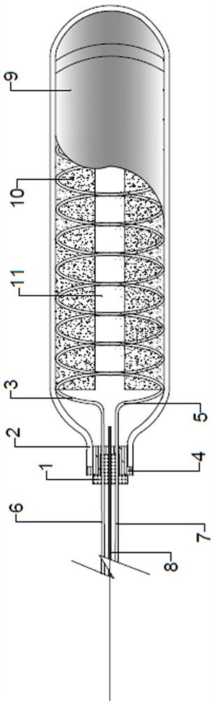
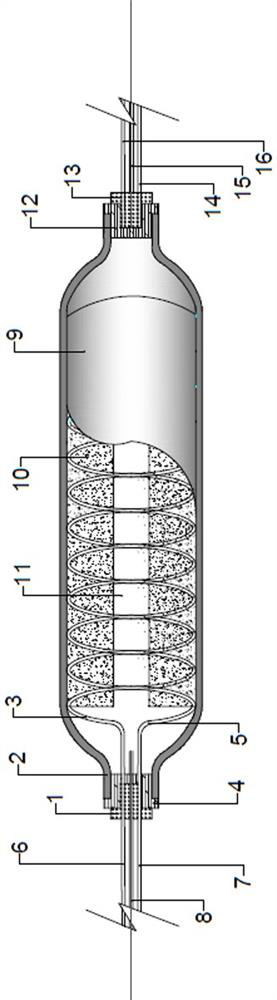
[0027] Such as figure 1 A solid hydrogen source device for hydrogen fuel is shown, which includes a hydrogen storage tank 9, a diaphragm and heat exchange pipes 3, 5, the hydrogen storage tank is a low-pressure hydrogen storage tank, and the material of the hydrogen storage tank is Lightweight aluminum alloy, the wall thickness of the hydrogen storage tank is 0.5 cm, wherein: one end of the hydrogen storage tank 9 is provided with a tank mouth 2, which is used to control the installation of the valve 1 that hydrogen enters the hydrogen storage tank 9 or discharges from the hydrogen storage tank 9 At the position of the tank mouth 2, a sealing ring 4 is installed between the valve 1 and the tank mouth 2; the heat exchange pipes 3, 5 are fixed on the inner wall of the hydrogen storage tank 9 in a double helix structure, and the heat exchange pipes 3, 5 are fixed on the inner wall of the hydrogen storage tank 9. The material of 5 is a copper tube with a diameter of 0.5 cm. The he...

Embodiment 2

[0030] Filling operation according to the mode of example one, the difference between the second embodiment and the first embodiment is that the material of the solid hydrogen storage alloy powder filled in the material bin 10 is different, and the material of the solid hydrogen storage alloy powder in the second embodiment is LaNi 4.85 al 0.15 Hydrogen storage alloy powder, the hydrogen storage capacity is 1.41 wt.% (mass percentage), the filling mass is 22 Kg, the particle size of the solid hydrogen storage alloy powder is 400 mesh, which can provide 0.2 MPa of hydrogen at 20 °C, With water as heat and mass transfer, when heated to 80°C, it can provide 5.6MPa of hydrogen.

Embodiment 3

[0032] Filling operation according to the mode of example one, the difference between the present embodiment three and the embodiment one is that the material of the solid hydrogen storage alloy powder filled in the material bin 10 is different, and the material of the solid hydrogen storage alloy powder in the present embodiment three is La 0.8 Ce 0.2 Ni 4.8 co 0.1 al 0.1 Hydrogen storage alloy, the difference is that the particle size of the solid hydrogen storage alloy powder is 300 mesh, the hydrogen storage capacity is 1.33 wt.% (mass percentage), and the filling quality is 18 Kg, which can provide 0.46 MPa at 20 °C Hydrogen, using oil as heat and mass transfer, can provide 10 MPa of hydrogen when heated to 125°C.

[0033] Comparing the results of the first to third examples above, it can be seen that the hydrogen capacity of the solid hydrogen source device provided by the present invention is mainly determined by the material of the filled alloy powder, and its hydro...


PUM

PropertyMeasurementUnit
particle size (mesh)aaaaaaaaaa

Abstract

The invention relates to a solid hydrogen source device for hydrogen fuel, and belongs to the technical field of hydrogen storage devices. Safety, portability and environmental adaptability of a solidhydrogen source to hydrogen utilization are achieved. According to the solution, a tank opening is formed in a hydrogen storage tank, a valve is mounted at the tank opening, a sealing ring is mountedbetween the valve and the tank opening, a heat exchange pipeline is of a double-spiral structure and is fixedly arranged on the inner wall of the hydrogen storage tank in a coiling manner, and a heatmass transfer inlet and a heat mass transfer outlet of the heat exchange pipeline respectively penetrate through the valve and extend to the outside of the hydrogen storage tank; a cavity is formed in the axis position in a tank body of the hydrogen storage tank, a hydrogen charging/discharging pipeline penetrates through the valve and communicates with the cavity, a plurality of material bins are arranged on the periphery of the cavity, the size of each material bin is not smaller than 4/5 of that of an inner cavity of the tank body of the hydrogen storage tank, a diaphragm is arranged on aside wall of each material bin, and the material bins are filled with solid hydrogen storage alloy powder. The device is simple in structure, safe, efficient, portable and suitable for various environments and has good reproducibility and stability.

Description

technical field [0001] The invention belongs to the technical field of hydrogen storage devices, and in particular relates to a solid hydrogen source device for hydrogen fuel. Background technique [0002] As a clean and efficient energy source, hydrogen energy has attracted widespread attention, especially in the application of energy and power, such as hydrogen vehicles and hydrogen fuel cell vehicles. Because it not only has high energy density, but also does not produce exhaust that pollutes the environment. However, the current storage methods for hydrogen are mainly high-pressure compression storage and low-temperature liquid storage. Although this hydrogen storage method is simple to operate and has fast hydrogen desorption kinetics, it is not safe due to the need to maintain high storage pressure and low hydrogen storage temperature and the requirements for the tank itself. Portability and environmental adaptability are not suitable for use as a fuel (power hydroge...

Claims


Application Information

Patent Timeline
Patent Type & Authority Applications(China)
IPC IPC(8): F17C1/12F17C1/14F17C13/04F17C13/00H01M8/04082H01M8/04089
CPCF17C1/12F17C1/14F17C13/04F17C13/00H01M8/04201H01M8/04216H01M8/04089F17C2201/0109F17C2201/035F17C2203/037F17C2205/0323F17C2221/012F17C2225/0138F17C2227/0309F17C2270/0178F17C2270/0184Y02E60/32Y02E60/50
Inventor 雍辉胡季帆
Owner TAIYUAN UNIVERSITY OF SCIENCE AND TECHNOLOGY
Why Eureka
Try Eureka