
Droplet power generation device and using method thereof

A power generation device, droplet technology, applied in the direction of circuit devices, battery circuit devices, friction generators, etc., can solve the problems of difficult installation of equipment, poor power generation effect, etc., and achieve high power generation efficiency

Pending Publication Date: 2020-12-11
GUANGDONG UNIV OF TECH
View PDF2 Cites 7 Cited by
  • Summary
  • Abstract
  • Description
  • Claims
  • Application Information

AI Technical Summary

Problems solved by technology

[0005] In order to overcome the defects that the equipment described in the prior art is difficult to install and the power generation effect is not good, the present invention provides a droplet power generation device, which can effectively use low-frequency disordered water motion energy to collect liquid droplets and The electric energy generated when the surface of the flat plate is in contact has a high power generation efficiency

Method used


Image

  • Droplet power generation device and using method thereof
  • Droplet power generation device and using method thereof

Examples


Embodiment 1

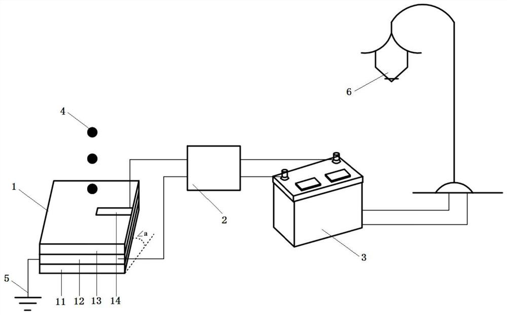
[0048] This embodiment provides a droplet power generation device, the schematic diagram is as follows figure 1 As shown, it includes a droplet power generation unit 1 and an electric storage unit.

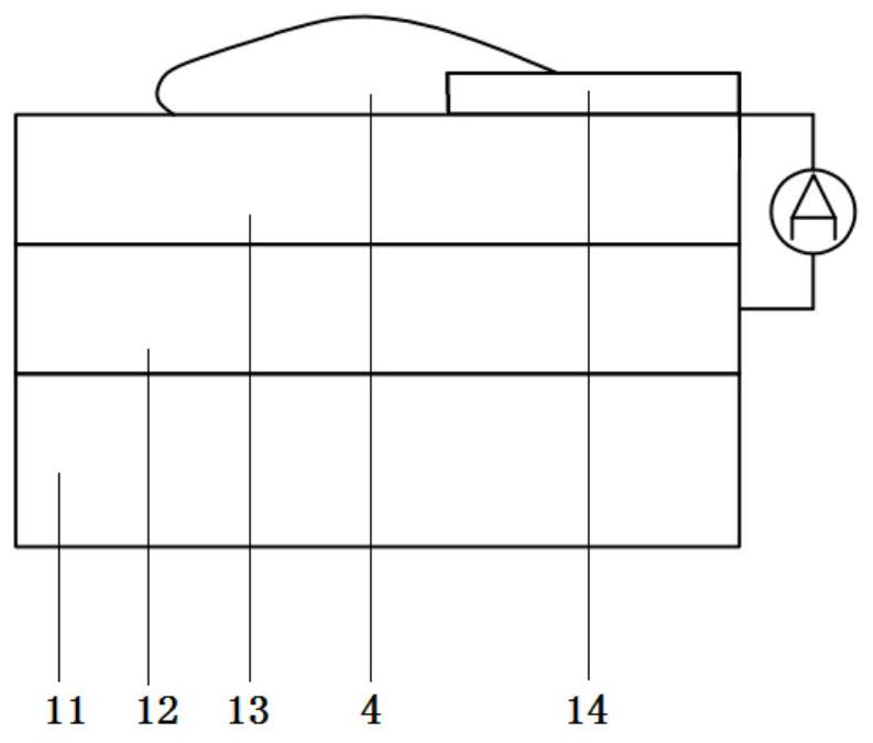
[0049] Wherein the droplet power generation unit 1 is sequentially provided with: a glass bottom plate 11, a graphene conductive film 12, a polytetrafluoroethylene film 13 and an aluminum electrode sheet 14 from bottom to top;

[0050] The size of the glass base plate 11 is 30mm × 30mm, and the size of the graphene conductive film 12 is 30mm × 30mm. The graphene conductive film 12 is deposited on the glass base plate 11 by chemical vapor phase deposition, and the total thickness of the glass base plate 11 and the graphene conductive film 12 is 0.4mm, the thickness of the polytetrafluoroethylene film 13 is 16.9 μm, the size of the aluminum electrode sheet 14 is 1mm×5mm, the thickness of the aluminum electrode sheet 14 is 50 μm, the polytetrafluoroethylene film 13 and the aluminum e...

Embodiment 2

[0060] This embodiment provides a droplet power generation device, which is different from Embodiment 1 in that the inclination angle a=10° of the droplet power generation unit 1 is adjusted during use.

[0061] When the number of droplet impacts reaches 16,000 times, the surface charge of the PTFE film reaches saturation, and the maximum instantaneous peak power density can reach 29.8W / m 2 .

Embodiment 3

[0063] This embodiment provides a droplet power generation device, which is different from Embodiment 1 in that the inclination angle a=80° of the droplet power generation unit 1 is adjusted during use.

[0064] When the number of droplet impacts reaches 18,000, the surface charge of the PTFE film reaches saturation, and the maximum instantaneous peak power density can reach 43.2W / m 2 .


PUM

PropertyMeasurementUnit
thicknessaaaaaaaaaa
angleaaaaaaaaaa
angleaaaaaaaaaa

Abstract

The invention discloses a droplet power generation device and a use method. The liquid drop power generation device comprises a liquid drop power generation unit and a power storage unit; the dropletpower generation unit comprises an insulating bottom plate, a first electrode, a polytetrafluoroethylene film and a second electrode which are sequentially arranged from bottom to top, wherein the second electrode is partially laid on the polytetrafluoroethylene film; the first electrode is further provided with a ground wire making contact with the ground. the power storage unit comprises a rectifier and a storage battery, the rectifier is connected with the first electrode and the second electrode through wires, and the storage battery is connected with the rectifier. The droplet power generation device provided by the invention can effectively utilize low-frequency disordered water motion energy to collect electric energy generated when droplets are in contact with the surface of a flatplate, and has relatively high power generation efficiency by combining the structural design of a field effect transistor and high surface charge density.

Description

technical field [0001] The invention relates to the field of new energy power generation, and more specifically, to a droplet power generation device and a method for using the same. Background technique [0002] With the continuous development of economic construction, my country's demand for electric energy is increasing. At this stage, environmental protection requirements are increasing, and it is of great practical significance to vigorously develop clean and efficient new energy power generation technologies. At present, technologies such as hydroelectric power generation and tidal power generation have matured. Most of the existing hydraulic generators are large-scale hydroelectric generators, which use high-frequency and large-volume liquids to drive large-scale hydroelectric generators to generate electricity. However, these technologies can only use the medium and high frequency motion of the liquid, and cannot efficiently collect low-frequency disordered water dr...

Claims


Application Information

Patent Timeline
Patent Type & Authority Applications(China)
IPC IPC(8): H02N1/04H02N1/08H02J7/32
CPCH02J7/32H02N1/04H02N1/08
Inventor 胡艳鑫林琳黄金颜奕波陈泽雄谢晓雪
Owner GUANGDONG UNIV OF TECH
Learn More