Preparation method and application of ammonium perchlorate thermal decomposition catalytic material

A catalytic material, ammonium perchlorate technology, applied in chemical instruments and methods, non-explosive/non-thermal agent components, physical/chemical process catalysts, etc., can solve the problems of poor catalytic performance of AP thermal decomposition, etc., to increase catalytic activity site, good application prospects, and the effect of increasing the specific surface area

Pending Publication Date: 2020-12-25
SHANGHAI INST OF TECH
View PDF6 Cites 4 Cited by
  • Summary
  • Abstract
  • Description
  • Claims
  • Application Information

AI Technical Summary

Problems solved by technology

[0005] The technical problem to be solved by the present invention is: existing CuCo ...

Method used


Image

  • Preparation method and application of ammonium perchlorate thermal decomposition catalytic material
  • Preparation method and application of ammonium perchlorate thermal decomposition catalytic material
  • Preparation method and application of ammonium perchlorate thermal decomposition catalytic material

Examples


Embodiment 1

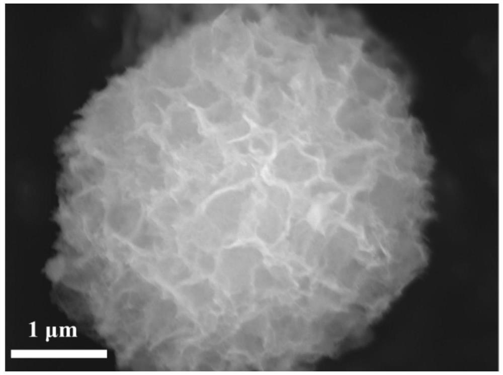
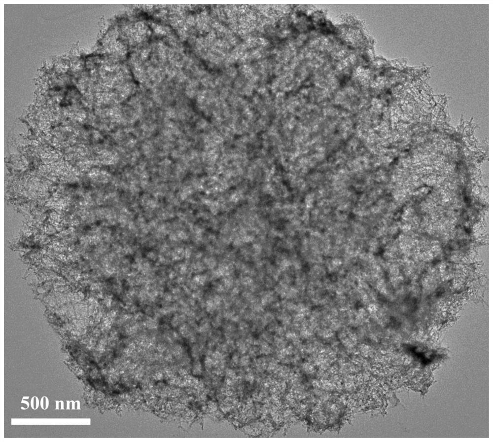
[0023] 4mmol Co(NO 3 ) 2 ·6H 2 O, 2mmol Cu(NO 3 ) 2 ·6H 2 O and 12 mmol urea were dissolved in 50 mL of polyethylene glycol 200 (PEG-200) to form a transparent pink solution, then the above mixture solution was transferred to a stainless steel reaction kettle containing a polytetrafluoroethylene liner, and reacted at 180 °C 12 hours. After natural cooling to room temperature, the resulting solid was filtered, washed thoroughly with deionized water and ethanol three times, and dried in an oven at 60 °C to obtain nanoflower-like CuCo 2 o 4 product.

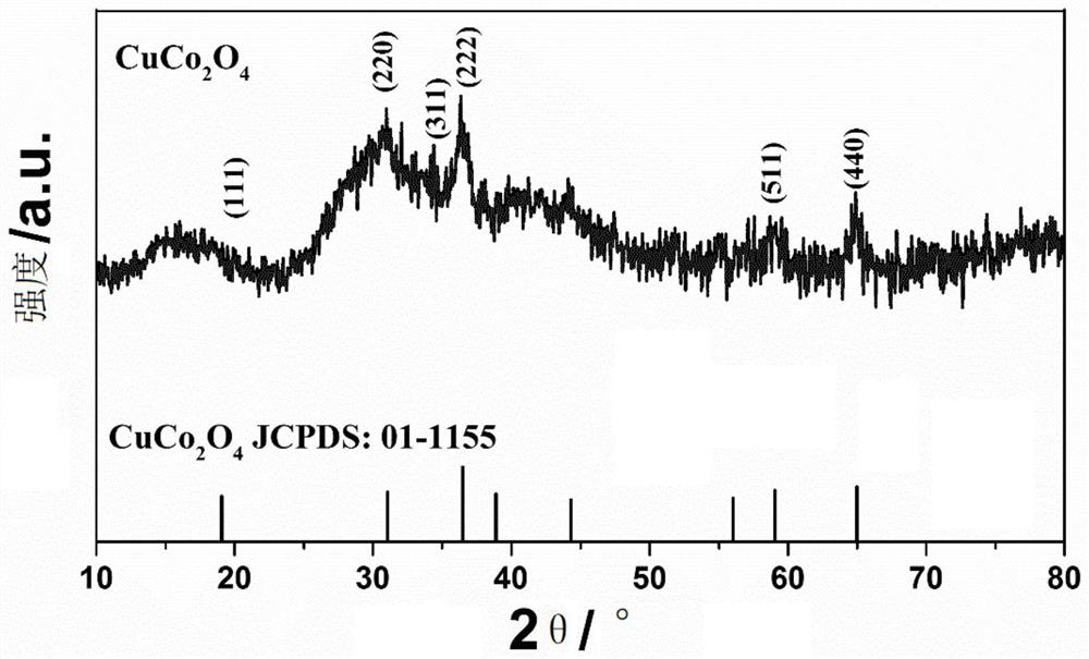
[0024] figure 1 For the nano-flower-like structure CuCo prepared in Example 1 2 o 4 XRD phase analysis of materials, from figure 1 It can be seen that CuCo 2 o 4 All the diffraction peaks and corresponding diffraction crystal planes in the sample are consistent with the spinel structure CuCo 2 o 4 The standard data (JCPDS Card No.01-1155) is consistent. The spectrum does not show any other impurity peaks, indicating ...

Embodiment 2

[0027] 4mmol Co(NO 3 ) 2 ·6H 2 O, 2mmol Cu(NO 3 ) 2 ·6H 2 O and 12 mmol of urea were dissolved in 50 mL of polyethylene glycol 200 (PEG-200) to form a transparent pink solution, then the above mixture solution was transferred to a stainless steel reaction kettle containing a polytetrafluoroethylene liner, and reacted at 200 °C 12 hours. After natural cooling to room temperature, the resulting solid was filtered, washed thoroughly with deionized water and ethanol three times, and dried in an oven at 60 °C to obtain nanoflower-like CuCo 2 o 4 product.

Embodiment 3

[0029] 4mmol Co(NO 3 ) 2 ·6H 2 O, 2mmol Cu(NO 3 ) 2 ·6H2 O and 12 mmol of urea were dissolved in 50 mL of polyethylene glycol 200 (PEG-200) to form a transparent pink solution, and then the above mixture solution was transferred to a stainless steel reactor containing a polytetrafluoroethylene liner and reacted at 160 °C 12 hours. After natural cooling to room temperature, the resulting solid was filtered, washed thoroughly with deionized water and ethanol three times, and dried in an oven at 60 °C to obtain nanoflower-like CuCo 2 o 4 product.


PUM

PropertyMeasurementUnit
Diameteraaaaaaaaaa
Diameteraaaaaaaaaa

Abstract

The invention discloses a preparation method of an ammonium perchlorate thermal decomposition catalytic material and application of the ammonium perchlorate thermal decomposition catalytic material incatalyzing thermal decomposition of ammonium perchlorate. The preparation method comprises the following steps of: dissolving Co(NO3)2.6H2O, Cu(NO3)2.6H2O and urea in polyethylene glycol to form a transparent pink solution, transferring the solution into a stainless steel reaction kettle containing a polytetrafluoroethylene liner, reacting at 160-220 DEG C for 10-24 hours, and preparing the nanoflower-like structure CuCo2O4 catalytic material for thermal decomposition of ammonium perchlorate by a solvothermal method. By optimizing the process route and reducing the cost, the invention provides a simple and practical method for preparing the bimetallic CuCo2O4 nano material, and the bimetallic CuCo2O4 nano material has important scientific value and development prospect in the field.

Description

technical field [0001] The invention relates to a preparation method and application of an ammonium perchlorate thermal decomposition catalytic material, and belongs to the technical field of nanometer material preparation and energetic materials. Background technique [0002] Due to their special properties such as large specific surface area and high surface activity, nanomaterials are widely used in the field of catalysis, such as photoelectric catalysis, biocatalysis and organic reactions. In recent years, more and more studies have reported the use of nanomaterials as combustion catalysts for solid propellants. Ammonium perchlorate (AP) is an oxidant and high-energy component widely used in composite solid rocket propellants, and it occupies a large proportion in the propellant, which can reach 65% to 90%. The thermal decomposition performance of AP directly affects the overall combustion performance of solid propellants. Therefore, it is of great significance to stud...

Claims


Application Information

Patent Timeline
IPC IPC(8): C01G51/00B82Y40/00C06B23/00B01J23/75B01J35/10
CPCC01G51/40B82Y40/00B01J23/75B01J23/002B01J35/1004C06B23/007C01P2004/30C01P2002/72C01P2004/03C01P2004/04C01P2002/88C01P2004/61
Inventor 徐小威李桂华常圣泉姜夏冰贾润萍
Owner SHANGHAI INST OF TECH
Why Eureka
Try Eureka