
Replacement scaphoid bone used in orthopedic surgery

A technology of orthopedic surgery and scaphoid, which is applied in medical science, bone implants, additive manufacturing, etc., can solve the problems of long recovery time and difficult recovery of scaphoid, and achieve the goals of facilitating recovery, promoting joint recovery, and reducing weight Effect

Pending Publication Date: 2020-12-29
湖南华翔医疗科技有限公司
View PDF4 Cites 1 Cited by
  • Summary
  • Abstract
  • Description
  • Claims
  • Application Information

AI Technical Summary

Problems solved by technology

[0011] The purpose of the present invention is just to solve the problem that the scaphoid rehabilitation time is long and the rehabilitation is difficult in the prior art

Method used


Image

  • Replacement scaphoid bone used in orthopedic surgery
  • Replacement scaphoid bone used in orthopedic surgery
  • Replacement scaphoid bone used in orthopedic surgery

Examples


Embodiment 1

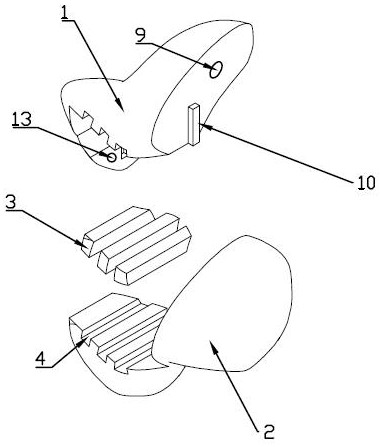
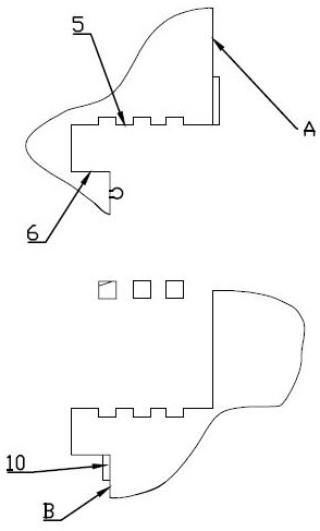
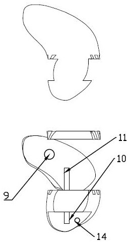
[0047] A replacement navicular bone used in orthopedic surgery, see Figure 1 to Figure 10 The replacement scaphoid used in the design of orthopedic surgery includes an upper bone block 1, a lower bone block 2, and a limit block 3 that limits the assembly direction and assembly angle freedom of the upper bone block 1 and the lower bone block 2. The upper bone block 1. The lower bone block 2 and the limiting block 3 include a 3D printed metal tantalum structure. The upper bone block 1, the lower bone block 2 and the limiting block 3 form a scaphoid-like assembly, which includes apertures from the inside out The metal holes are successively reduced, and the two ends of the limit block 3 are provided with surgical suture cavities 4 to suture the fascia and the assembly, and the mating surface of the replacement scaphoid and surrounding bone is coated with a polishing layer. During the operation, the original bone to be replaced is firstly taken out, and then the upper bone block ...

Embodiment 2

[0056] The principle of this embodiment is the same as that of Embodiment 1, the specific difference is that, as Figure 9 , the position of the "["-shaped section is replaced by an inclined setting relative to the horizontal plane, and the inclination angle corresponds to the design angle that maximizes the assembly length of the cross section. In order to adapt to the changes made according to the specific situation when the related joints also have lesions and need special treatment.

[0057] The waist of the replacement scaphoid formed by the combination is provided with a reinforcement element, and the reinforcement element includes a reinforcement belt designed around the waist with a width greater than 3mm, and the diameter of the metal hole on the reinforcement belt is less than 2mm.

[0058] An auxiliary positioning element is provided between the limiting block 3 and the section, and the auxiliary positioning element includes self-locking blocks and grooves 14 respec...


PUM

PropertyMeasurementUnit
Sizeaaaaaaaaaa
Widthaaaaaaaaaa
Apertureaaaaaaaaaa

Abstract

The invention relates to the field of interventional equipment used in orthopedic surgery, in particular to a replacement scaphoid bone used in orthopedic surgery. The problems that in the prior art,scaphoid rehabilitation time is long, and rehabilitation difficulty is large are solved. The artificial scaphoid bone comprises an upper bone block, a lower bone block and a limiting block for limiting the assembling directions and the assembling angle freedom degrees of the matching state of the upper bone block and the lower bone block, the upper bone block, the lower bone block and the limitingblock comprise metal tantalum structures formed through 3D printing, and the upper bone block, the lower bone block and the limiting block form an artificial scaphoid bone combination body. The assembly comprises metal holes with the hole diameters sequentially decreased from inside to outside, and operation suture cavities are formed in the two ends of the limiting block so as to suture fascia and the assembly. The scaphoid bone for replacement has the advantages that firstly, the scaphoid bone replacement time can be shortened, and secondly, the postoperative use strength and use flexibility can be guaranteed, which are not possessed by previous products.

Description

technical field [0001] The invention relates to the field of replacement navicular bone used in orthopedic surgery, in particular to a replacement navicular bone used in orthopedic surgery. Background technique [0002] Scaphoid fracture is a common clinical fracture, accounting for 2% of systemic fractures and 70% to 80% of carpal fractures, second only to distal radius fractures. There are many methods for the clinical treatment of scaphoid fractures, but there is no clear selection criteria yet. If left untreated or wrongly treated, complications such as severe malunion, nonunion, aseptic ischemic necrosis, and hypertrophic scar pain may easily occur. Navicular osteonecrosis is prone to occur after scaphoid fracture, and there is currently no good treatment. At present, tendon ball transplantation or carpal fusion is mainly used for treatment, but the effect is not satisfactory. Anatomical features of navicular bone: Irregular structure. [0003] The scaphoid is long ...

Claims


Application Information

Patent Timeline
IPC IPC(8): A61F2/28A61F2/30A61F2/42
CPCA61F2/2846A61F2/4261A61F2/30942A61F2/30767A61F2002/4289A61F2002/30985A61F2002/30769A61F2002/30024A61F2310/00131
Inventor 段家骐王国华刘江宋坤邹炜民
Owner 湖南华翔医疗科技有限公司
Learn More