A Surface Treatment Method of Ultrathin Polymer
A surface treatment and polymer technology, applied in the field of ion beam coating, can solve the problems of limiting the wide application of ultra-thin polymers, difficult to achieve copper cladding treatment, low surface bonding strength, etc., to achieve a balance between surface resistivity, low cost, The effect of enhanced peel strength
- Summary
- Abstract
- Description
- Claims
- Application Information
AI Technical Summary
Problems solved by technology
Method used
Image
Examples
Embodiment 1
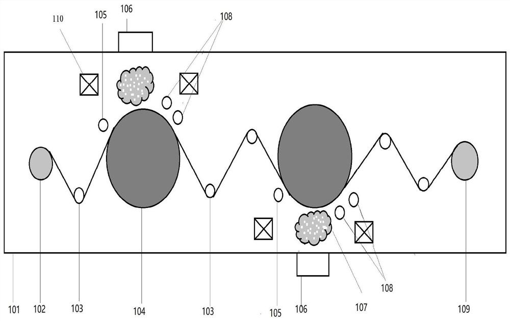
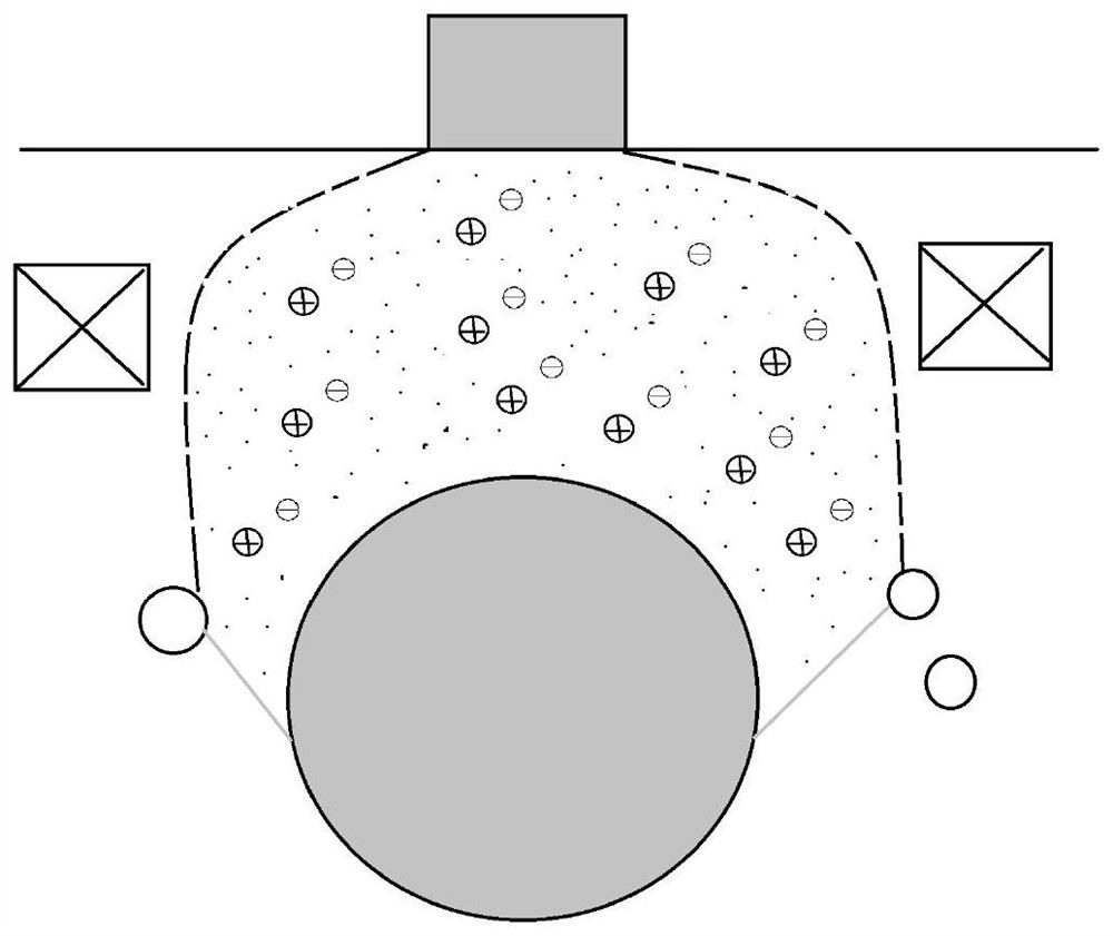
[0037] Such as figure 1 , figure 2 as shown,
[0038] A surface treatment method for ultra-thin polymers, carried out in a vacuum chamber, the pressure in the vacuum chamber is 2×10 - 2 Pa, the air pressure fluctuation range does not exceed 5%. The surface treatment method includes fixing the polymer film on the unwinding shaft, and moving the polymer film to the cooling roll under the action of the guide roller for ion beam surface treatment. After the surface treatment, it continues to move to the winding shaft under the action of the guide roller ; The electric field strength between the cold roller and the vacuum chamber wall is not lower than 250V / m; the magnetron system includes twin target magnetron sputtering, and its magnetic field strength is 50mT. The thickness of the polymer film is less than 5 microns, and the ion beam surface treatment is performed twice.
[0039] The device for ion beam surface treatment includes an ion source system, an arc system, and a ...
Embodiment 2
[0044] Compared with embodiment 1, the difference is as follows:
[0045] The linear distance between the gas ion source and the center of the arc cathode surface is 320 mm, and the angle between the line and the vertical is 40 degrees; the gas ion source is 100 mm away from the surface of the cold roll, and the center of the gas ion source is 40 mm lower than the center of the cold roll; the magnetic control system The distance between the center and the surface of the cold roll is 60mm, and the linear distance from the center of the arc cathode surface is 350mm;
[0046] S1: The polymer film is treated with a gas ion source before copper is deposited on the surface, the air intake is 200sccm, the Penning source voltage is 20KV, and the gas ion beam current is 500mA;
[0047] S2: The starting current of the arc deposition in the arc system is 30A, and the current is 0.1-1A; the magnetron sputtering current in the magnetron system is 0.1-2A. The electric field strength betwee...
Embodiment 3
[0049] Compared with embodiment 1, the difference is as follows:
[0050] The linear distance between the gas ion source and the center of the arc cathode surface is 310 mm, and the angle between the line and the vertical is 38 degrees; the gas ion source is 80 mm away from the surface of the cold roll, and the center of the gas ion source is 35 mm lower than the center of the cold roll; the magnetic control system The distance between the center and the surface of the cold roll is 55mm, and the linear distance from the center of the arc cathode surface is 330mm;
[0051] S1: The polymer film is treated with a gas ion source before copper is deposited on the surface, the air intake is 200sccm, the Penning source voltage is 30KV, and the gas ion beam current is 500mA;
[0052] S2: The starting current of the arc deposition in the arc system is 30A, and the current is 0.1-1A; the magnetron sputtering current in the magnetron system is 0.1-2A. The electric field strength between...
PUM
| Property | Measurement | Unit |
|---|---|---|
| thickness | aaaaa | aaaaa |
| thickness | aaaaa | aaaaa |
Abstract
Description
Claims
Application Information
 - R&D
- Intellectual Property
- Life Sciences
- Materials
- Tech Scout
- Unparalleled Data Quality
- Higher Quality Content
- 60% Fewer Hallucinations
Browse by: Latest US Patents, China's latest patents, Technical Efficacy Thesaurus, Application Domain, Technology Topic, Popular Technical Reports.
© 2025 PatSnap. All rights reserved.Legal|Privacy policy|Modern Slavery Act Transparency Statement|Sitemap|About US| Contact US: help@patsnap.com


