

Environment-friendly and energy-saving dust suppression system for hot slag braising process and using method thereof
An energy-saving, hot slag technology, applied in the separation method, the use of liquid separation agent, cleaning methods and appliances, etc., can solve the problems of secondary pollution, large roof dust removal air volume, difficult transformation, etc., to reduce water and air consumption , the effect of energy saving is remarkable, and the effect of improving the combination efficiency
- Summary
- Abstract
- Description
- Claims
- Application Information
AI Technical Summary
Problems solved by technology
Method used
Image

Examples
Embodiment 1
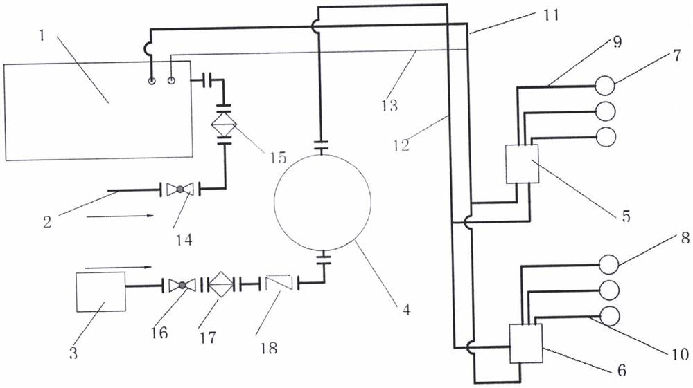
[0026] Please refer to the accompanying drawings of the description. In the embodiment of the present invention, an environmental protection and energy-saving thermal slag process dust suppression system includes a main engine 1, a water inlet pipe 2, a water pipe 11, an air compressor 3, an air storage tank 4, a ventilation pipe 12, Large spray gun distributor 6, lotus nozzle distributor 5, four slag pools and two vibrating screens, wherein one end of the main machine 1 is connected to the water inlet pipe 2, and the front end of the water inlet pipe 2 is installed with a water inlet Valve 14, a water filter 15 is installed between the water inlet pipe 14 and the host 1, and the host 1 communicates with the large spray gun distributor 6 and the lotus spray nozzle distributor 5 through the water pipe 11 respectively; the air compressor 3 is connected with the The air storage tanks 4 are communicated with each other through a vent pipe 12, and a vent valve 16, an air filter 3, a...
Embodiment 2
[0046] An environment-friendly and energy-saving method for using a dust suppression system for hot slag slag process, wherein,
[0047] S1: Conduct the dust inhibitor ratio experiment through the dispensing box, select the best ratio of dust inhibitor to water, the ratio of dust inhibitor to water: the range is 1:400-1:1000;
[0048] S2: After completing the dust inhibitor ratio experiment, then set the host 1, and then start the host 1 for dust suppression, and start the air compressor 3 at the same time, and supply the compressed air to the air storage tank through the air filter 17 4;
[0049] S3: After the pressure of the air storage tank 4 is stabilized, the stable compressed air is supplied to the large spray gun distributor 6 and the lotus nozzle distributor 5 according to the flow rate set by the PLC control system, and the host 1 receives the water supplied by the water source and the air storage tank 4 Provide stable compressed air;
[0050] S4: The host 1 filters...
PUM
 Abstract
Description
Claims
Application Information